2 Design
2 - 18
High-function General-purpose Inverter 3G3RX-V1 User’s Manual (I578-E1)
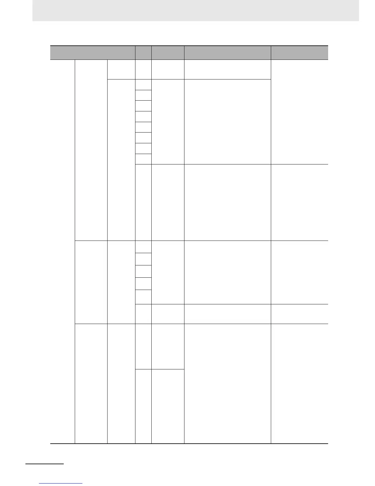
Digital
(contact)
Contact input
RUN
command
FW
Forward RUN
command
terminal
When the FW signal is ON, the motor
runs forward. When it is OFF, the motor
decelerates and stops.
[Contact input ON
condition]
Voltage between each
input terminal and the
terminal PSC: 18 VDC or
more
Input impedance between
each input terminal and
the terminal PSC: 4.7 kΩ
Max. allowable voltage:
Voltage between each
input terminal and the
terminal PSC: 27 VDC
Load current at 27 VDC
power supply voltage:
Approx. 5.6 mA
Function,
switching,
etc.
S1
Multi-function
input
Select 8 functions from among the 70
functions and allocate them to terminals
S1 to S8.
S2
S3
S4
S5
S6
S7
S8
PSC
Multi-function
input
common
The sink and source logics for contact
input can be switched by connecting a
short-circuit bar on the control terminal
block.
• Short-circuiting P24 and SC:
Sink logic
• Short-circuiting SC and PSC:
Source logic
To activate contact input via an external
power supply, remove the short-circuit
bar and connect terminal PSC to the
external interface circuit.
–
Open
collector
output
Status,
factor, etc.
P1
Multi-function
output
Select five functions from among 52
functions, and allocate them to terminals
P1 through P5.
When an alarm code is selected in
C062, terminals P1 to P3, or terminals
P1 to P4 always output an alarm factor
code (e.g. inverter trip).
The signal between each terminal and
PC always corresponds to the sink or
source logic.
Between each terminal
and PC
Voltage drop at power-on:
4 V max.
Max. allowable voltage:
27 VDC
Max. allowable current:
50 mA
P2
P3
P4
P5
PC
Multi-function
output
common
Common terminal for multi-function
output terminals P1 to P5.
–
Relay output
Status,
alarm, etc.
MA
MB
Multi-function
relay output
Select the desired function from among
52 functions, and allocate it to these
ter
minals.
SPDT contact output.
By factory default, Multi-function Rela
y
Output (MA, MB) Operation Selection
(C036) is set at NC contact between MA
and MC, and NO contact between MB
and MC.
Max. contact capacity
Between MA and MC
• 250 VAC:
2 A (Resistance)/0.2 A
(Induction)
• 30 VDC:
8 A (Resistance)/0.6 A
(Induction)
Between MB and MC
• 250 VAC:
1 A (Resistance)/0.2 A
(Induction)
• 30 VDC:
1 A (Resistance)/0.2 A
(Induction)
Min. contact capacity
• 100 VAC, 10 mA
• 5 VDC, 100 mA
MC
Multi-function
relay output
common
Terminal
Terminal
symbol
Terminal
name
Description Specifications
 Loading...


