3 Operation and Test Run
3 - 26
High-function General-purpose Inverter 3G3RX-V1 User’s Manual (I578-E1)
If no problem is found at power-on, the display status will be as follows.
If any problem is found, the display status will be as follows.
Take countermeasures according to Section 10 Troubleshooting.
You can initialize the changed parameters and also clear the fault monitor data.
As a measure to prevent inadvertent parameter initialization, the inverter is designed to force the user
to set several parameters to execute initialization.
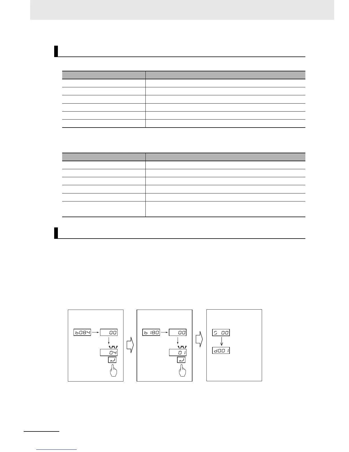
The following figure shows the steps of complete parameter initialization.
Complete initialization means to clear the Fault Monitor and DriveProgramming application data, as well
as the parameter data.
For details on parameter initialization, refer to 5-1 Parameter Display and Parameter Initialization on
page 5-3.
Display Status Checks
Name Display status
POWER LED Lit
ALARM LED Not lit
RUN LED Not lit (Lit during RUN)
RUN command LED indicator Lit
Data display LED (Hz) Lit
Data display Displays d001 setting.
Name Display status
POWER LED Lit
ALARM LED Lit
RUN LED Not lit
RUN command LED indicator Lit
Data display LED (Hz) Lit
Data display
Displays error code such as E01.
(Displayed error code differs depending on error condition.)
Parameter Initialization