Under sensorless vector control, 0-Hz sensorless vector control, or sensor vector control,
because of its control characteristics, the inverter may output a rotation signal opposite to the
RUN command direction at low speeds. If allowing the motors to rotate in the opposite rotation
may pose a risk of mechanical damage or any other problem, set the Reverse Rotation
Prevention Selection (b046) to 01 (Enabled). (Refer to Reverse Rotation Prevention Function on
page 7-83).
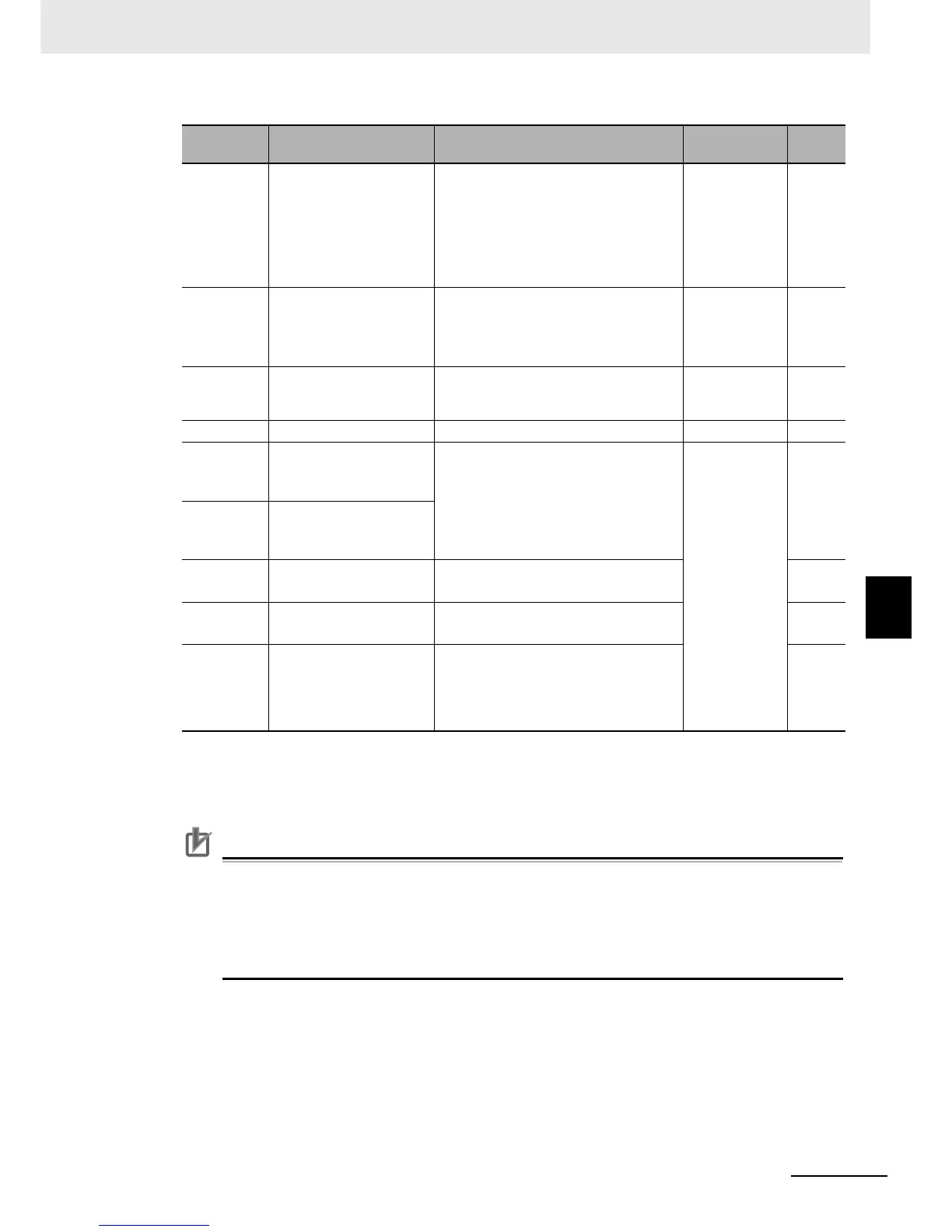
Parameter
No.
Function name Data Default data Unit
A044 1st Control Method
00: Constant torque characteristics (VC)
01: Reduced torque characteristics
02: Free V/f setting
03: Sensorless vector control
04: 0-Hz sensorless vector control
05: Sensor vector control (V2)
00 –
H002
1st Motor Parameter
selection
00: Standard motor parameter
01: Auto-tuning
02: Auto-tuning (Online auto-tuning
enabled)
00 –
H003 1st Motor Capacity
0.2/0.4/0.55/0.75/1.1/1.5/2.2/3.0/3.7/4.0/
5.5/7.5/11.0/15.0/18.5/22/30/37/45/55/
75/90/110/132
Maximum
applicable
motor capacity
kW
H004 1st Motor Pole Number 2/4/6/8/10 4 pole
H020
1st Motor Parameter R1
(Winding resistance on
primary side)
0.001 to 9.999
10.00 to 65.53
Dependent on
motor capacity
Ω
H021
1st Motor Parameter R2
(Winding resistance on
secondary side)
H022
1st Motor Parameter L
(Leakage inductance)
0.01 to 99.99
100.0 to 655.3
mH
H023
1st Motor Parameter Io
(No-load current)
0.01 to 99.99
100.0 to 655.3
A
H024
1st Motor Parameter J
(Moment of inertia)
0.001 to 9.999
*1
10.00 to 99.99
100.0 to 999.9
1000. to 9999.
*1. For the Moment of Inertia J, set the motor conversion value. The larger the J value, the higher the response
speed, which results in a steep torque rise; the smaller the J value, the lower the response speed, which
results in gradual torque rise. After setting the J value, adjust the response speed in the 1st/2nd Speed
Response (H005/H205).
kg/m
2
 Loading...


