11 Maintenance and Inspection
11 - 6
High-function General-purpose Inverter 3G3RX-V1 User's Manual (SBCE-367)
*1 The replacement interval (in years or cycles) shown here and the smoothing capacitor life curve provided in Appendix A-1
are based on the expected design life and not guaranteed data.
Note In case that you find any problems during inspection, contact your OMRON sales representative.
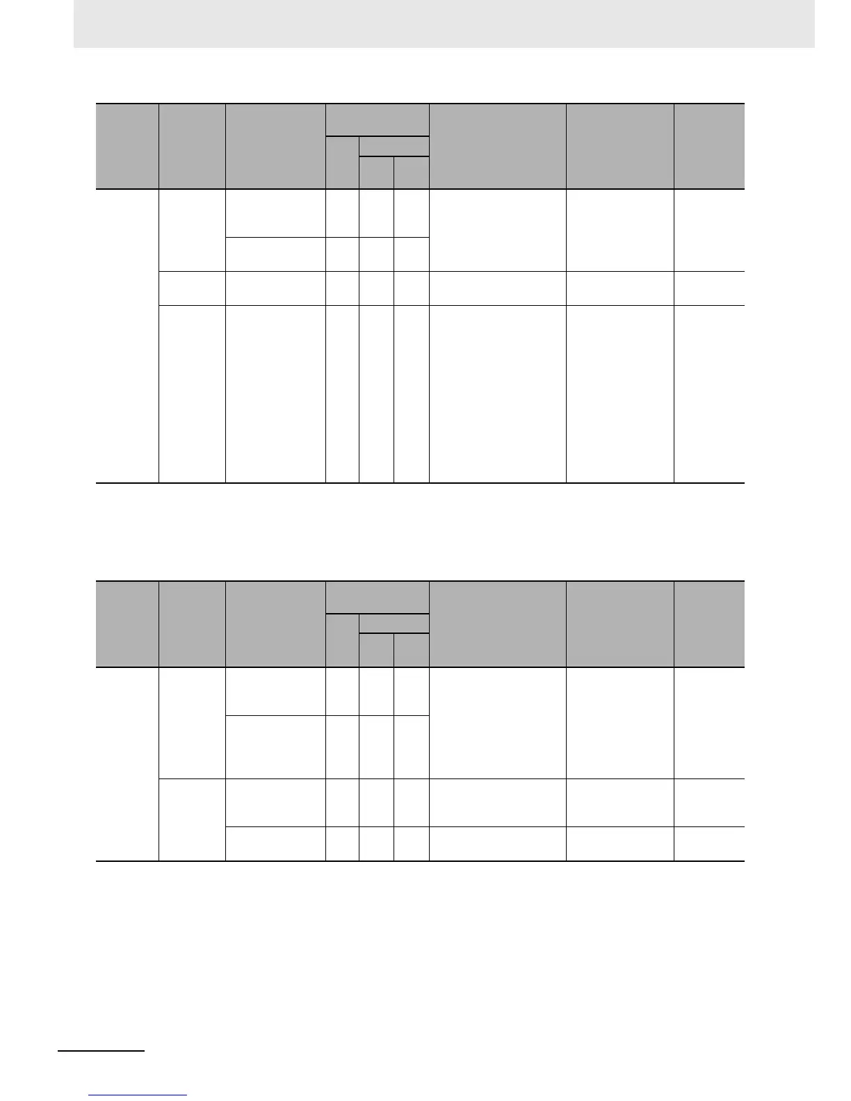
Main
circuit
Conductor/
wire
Check for
distorted
conductor.
Perform visual
inspection.
No faults
Check for broken
cable sheaths.
Ter m ina l
block
Check for
damage.
Perform visual
inspection.
No faults
Inverter
unit/
Converter
unit
(including
resistors)
Check resistance
between
terminals.
Disconnect wires from
the inverter main circuit
terminal block and
measure the resistance
between the terminals
R/L1, S/L2, T/L3 and
the terminals P/+2, N/–,
and between the
terminals U/T1, V/T2,
W/T3 and the terminals
P/+2, N/– using a tester
in the x1 Ω range.
Refer to 11-3-3
Inverter/Converter
Unit Test on page
11-10.
Inverter unit
replacement
interval:
10
6
start-stop
cycles
*1
Analog
tester
Inspection
category
Inspection
item
Inspection
point
Inspection
frequency
Inspection method Criteria Meter
Daily
Periodic
1
year
2
years
Main
circuit
Smoothing
capacitor
*1
Check that there
is no liquid
leakage.
Perform visual
inspection.
No faults
Replacement
interval:
10 years
*3
Capacity
meter
Check safety
valve for
protrusion and
swelling.
Relay
Check for
chattering sound
during operation.
Perform acoustic
inspection.
No faults
Check for rough
contact surface.
Perform visual
inspection.
No faults
Inspection
category
Inspection
item
Inspection
point
Inspection
frequency
Inspection method Criteria Meter
Daily
Periodic
1
year
2
years