2 Design
2 - 36
High-function General-purpose Inverter 3G3RX-V1 User’s Manual (I578-E1)
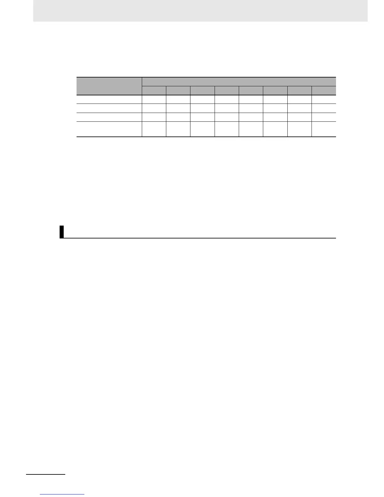
Effect of reactors
Through the use of the DC/AC reactor, the rate of harmonic current occurrences can be reduced as
shown in the table of typical examples below.
Guideline for reactor selection
When implementing measures against harmonics, first install a DC reactor and evaluate its effect.
Then, if further reduction is required, add an AC reactor.
To implement harmonic countermeasures in consideration of the power supply environment, first
install an AC reactor and evaluate its effect. Then, if further reduction is required, add a DC reactor.
If you have multiple inverters and use the AC reactor, use one AC reactor for each inverter. Using
only one AC reactor for more than one inverter does not provide sufficient reduction.
The following describes the wiring for the inverter output terminals (U/T1, V/T2, W/T3).
Never connect power supply to output terminals
Never connect the power supply to the output terminals U/T1, V/T2, W/T3.
The inverter is damaged internally if power supply voltage is applied to the output terminals.
Never short or ground output terminals
Do not touch the output terminals with bare hand or contact the output wires with the inverter’s case.
Doing so may result in electric shock or ground fault.
Be careful not to short the output wires.
Do not use phase advance capacitors/noise filters.
Never connect a phase advance capacitor or LC/RC noise filter for general-purpose power supplies
to the output circuit.
Doing so may result in damage to the inverter or burnout of these parts.
Do not use magnetic switches
Do not connect any magnetic switch or magnet contactor to the output circuit.
If a load is connected to the inverter in operation, the inverter’s overvoltage protection circuit is
activated due to the inrush current.
Measure against
harmonics
Harmonic current occurrence rate [%]
5th 7th 11th 13th 17th 19th 23rd 25th
None (Inverter only) 65 41 8.5 7.7 4.3 3.1 2.6 1.8
With AC reactor 38 14.5 7.4 3.4 3.2 1.9 1.7 1.3
With DC reactor 30 13 8.4 5 4.7 3.2 3.0 2.2
With DC and AC
Reactors
28 9.1 7.2 4.1 3.2 2.4 1.6 1.4
Wiring for Inverter Output Terminals (U/T1, V/T2, W/T3)
 Loading...


