EasyManua.ls Logo

Omron Sysmac NY-series User Manual

Omron Sysmac NY-series
744 pages
To Next Page IconTo Next Page
To Previous Page IconTo Previous Page
Page #267 background imageLoading...
Page #267 background image
0 60 120 180 240 300 360
0
50
100
150
200
250
300
350
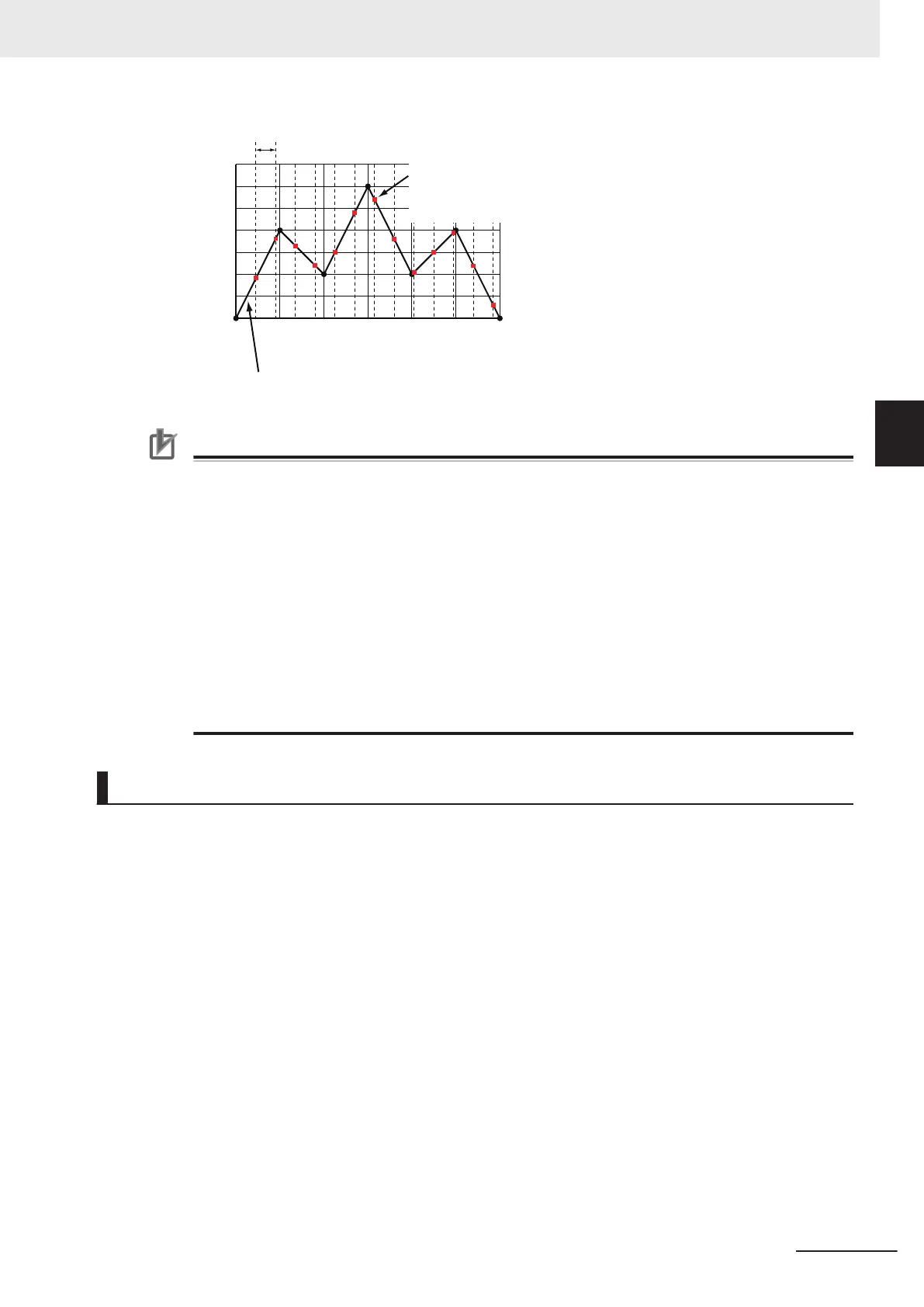
The phase is calculated from the master
axis position for each cycle. The linear
interpolation of cam data is used to
calculate displacements from the phases.
(These are the red dots on the line.)
Command position during electronic cam operation
1 cycle
Linearl
y interpolate between cam data (black dots on the line).
Phase
Displace-
ment
Precautions for Correct Use
When executed, this instruction checks if the phases are in ascending order. If they are not in
ascending order, an error occurs.
When you change cam data, execute the MC_SetCamTableProperty (Set Cam Table Proper-
ties) instruction to make sure that the phases are in ascending order.
Make sure that the phases will be in ascending order before you change the phases during a
cam motion. The cam motion may stop if the phases are not in ascending order.
Cam data variables are global variables. You can therefore access or change the values of
cam data variables from more than one task. If you change the values of cam data variables
from more than one task, program the changes so that there is no competition in writing the
value from more than one task.
If you use exclusive control of global variables between tasks for a cam data variable, do not
use the cam data variable for motion control instructions while exclusive control is in effect for
the cam data variable. An Incorrect Cam Table Specification error (error code: 5439 hex) will
occur.
Instruction Details
This section describes the instruction in detail.
Instruction Execution Condition
You can execute this instruction while the master axis is stopped, during position control, velocity con-
trol, or synchronized control.
For details on the slave axis, refer to Re-execution of Motion Control Instructions on page 3-199 and
Multi-execution of Motion Control Instructions on page 3-6.
Software Limits
If the slave axis exceeds the software limit during cam operation, an error occurs.
Cam Data Variables
A cam data variable is declared as an array of cam data structures. The type declaration for the cam
data structure is shown below.
3 Axis Command Instructions
3-179
NY-series Motion Control Instructions Reference Manual (W561)
MC_CamIn
3
Function

Table of Contents

Question and Answer IconNeed help?

Do you have a question about the Omron Sysmac NY-series and is the answer not in the manual?

Omron Sysmac NY-series Specifications

General IconGeneral
CategoryControl Unit
Operating Temperature0 to 55 °C
Power Supply Voltage24 VDC
Power Supply24 VDC
Product SeriesNY-series
CPUIntel Atom or Intel Core i7
Programming LanguagesIEC 61131-3 (LD, FBD, ST, SFC)
Memory (Program)Up to 64 MB
Ethernet Ports2
EtherNet/IP Ports2 ports (built-in)
EtherCAT Master Ports1
EtherCATYes
Motion ControlSupported
SafetyYes
Built-in I/ONo
Relative Humidity10 to 90% (non-condensing)
Vibration Resistance5 to 8.4 Hz: 3.5 mm; 8.4 to 150 Hz: 9.8 m/s²
Shock Resistance147 m/s²
Power ConsumptionVaries by model
CertificationsCE, cULus, RCM, KC, EAC

Summary

Introduction to Motion Control Instructions

Variables and Instructions

Axis Command Instructions

MC_Power

Explains the MC_Power instruction for making a Servo Drive ready to operate.

MC_MoveJog

Explains the MC_MoveJog instruction for jogging an axis according to the specified target velocity.

MC_Home

Explains the MC_Home instruction for operating the motor to determine home.

MC_HomeWithParameter

Explains the MC_HomeWithParameter instruction for setting homing parameters and operating the motor to determine home.

MC_Move

Explains the MC_Move instruction for performing absolute positioning or relative positioning.

MC_MoveAbsolute

Explains the MC_MoveAbsolute instruction for moving the axis to a specified absolute target position.

MC_MoveRelative

Explains the MC_MoveRelative instruction for moving the axis the specified travel distance.

MC_MoveVelocity

Explains the MC_MoveVelocity instruction for performing velocity control.

MC_MoveZeroPosition

Explains the MC_MoveZeroPosition instruction for positioning to an absolute position of 0.

MC_Stop

Explains the MC_Stop instruction for decelerating an axis to a stop.

MC_ImmediateStop

Explains the MC_ImmediateStop instruction for stopping an axis immediately according to the specified stopping mode.

MC_CamIn

Explains the MC_CamIn instruction to start cam operation using a specified cam table.

MC_GearIn

Explains the MC_GearIn instruction to specify the gear ratio and start gear operation.

MC_GearInPos

Explains the MC_GearInPos instruction to perform electronic gear operation with specified gear ratio.

MC_MoveLink

Explains the MC_MoveLink instruction for positioning in sync with the specified master axis.

MC_TorqueControl

Explains the MC_TorqueControl instruction to control torque using the Torque Control Mode.

MC_SetTorqueLimit

Explains the MC_SetTorqueLimit instruction to limit torque output from the Servo Drive.

MC_TouchProbe

Explains the MC_TouchProbe instruction to record axis position when a trigger signal occurs.

MC_SyncMoveVelocity

Explains the MC_SyncMoveVelocity instruction for outputting target velocity in CSV Mode.

MC_SyncMoveAbsolute

Explains the MC_SyncMoveAbsolute instruction to cyclically output target positions.

MC_Reset

Explains the MC_Reset instruction to clear axis errors.

MC_DigitalCamSwitch

Explains the MC_DigitalCamSwitch instruction to turn a digital output ON or OFF based on axis position.

Axes Group Instructions

Common Command Instructions

Related product manuals