R&S
®
ZVA / R&S
®
ZVB / R&S
®
ZVT GUI Reference
Trace Menu
Operating Manual 1145.1084.12 – 30 124
and <in> denote the output (response) and input (stimulus) port numbers of the DUT.
Balanced and Measured Ports opens the Balanced Port and Port Groups dialog to define the
properties of the test ports. Single-ended (unbalanced) impedance parameters are assigned to
the physical test ports of the analyzer. Balanced impedance parameters are assigned to logical
test ports. Selecting a balanced port configuration with logical test ports means that the
unbalance-balance conversion is switched on and that the analyzer provides mixed mode
parameters.
The graphics above the Balanced and Measured Ports button illustrates the current port
configuration.
The port configuration is valid for all traces in the channel
The settings made in the Balanced and Measured Ports dialog are channel settings and therefore apply to
all traces assigned to the channel (Balanced and Measured Ports is also accessible through Channel –
Mode – Port Config...). Within a channel the analyzer measures either single-ended or mixed mode
parameters. If a balanced test port configuration is selected the single-ended parameters assigned to the
channel are converted into mixed mode parameters.
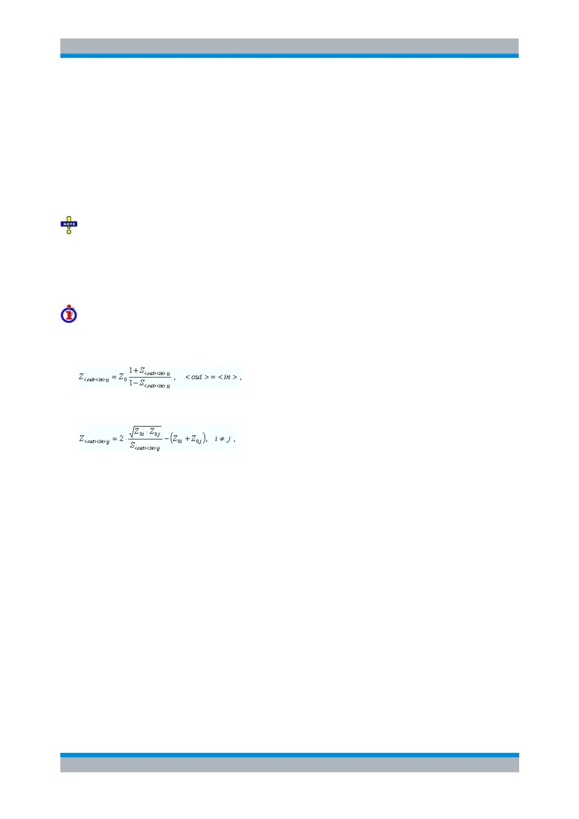
Relation between impedances and S-parameters
The relation between the generalized (multiport and mixed mode) impedance parameters and the S-
parameters is analogous to the 2-port case. For reflection measurements:
and for transmission measurements:
where Z
0i
denotes the reference impedance of the analyzer port no. i.
CALCulate<Ch>:PARameter:MEASure "<Trace_Name>", "Z-S11" | "Z-
S12" ...
Create new trace and select name and measurement parameter:
CALCulate<Ch>:PARameter:SDEFine "<Trace_Name>", "Z-S11" | "Z-
S22" | ...
Admittance
The Admittance submenu contains the functions to calculate converted admittances from the measured S-
parameters.