R&S
®
ZVA / R&S
®
ZVB / R&S
®
ZVT GUI Reference
Trace Menu
Operating Manual 1145.1084.12 – 30 126
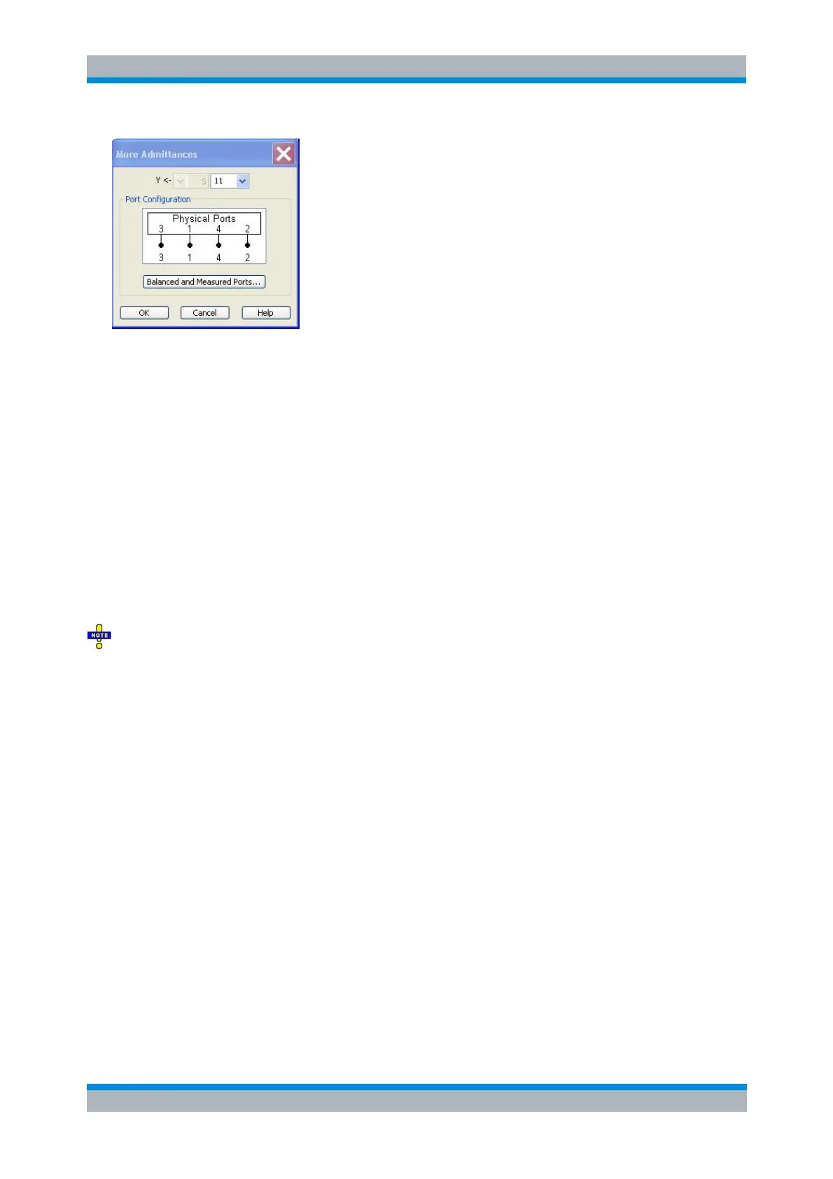
The notation for admittance parameters and the functionality of the More Admittances dialog is analogous
to the definition of S-parameters.
Y<— selects the type (left pull-down list) and the port number assignment (right pull-down list) of
the admittance parameter. Mixed mode parameters are only available if a balanced port
configuration is active. They are expressed as Y
<mout><min>
, where <mout> and <min> denote the
output and input port modes. The port numbers are assigned in the order Y
<out>< in>
, where <out>
and <in> denote the output (response) and input (stimulus) port numbers of the DUT.
Balanced and Measured Ports opens the Balanced Port and Port Groups dialog to define the
properties of the test ports. Single-ended (unbalanced) admittance parameters are assigned to
the physical test ports of the analyzer. Balanced admittance parameters are assigned to logical
test ports. Selecting a balanced port configuration with logical test ports means that the
unbalance-balance conversion is switched on and that the analyzer provides mixed mode
parameters.
The graphics above the Balanced and Measured Ports button illustrates the current port
configuration.
The port configuration is valid for all traces in the channel
The settings made in the Balanced and Measured Ports dialog are channel settings and therefore apply to
all traces assigned to the channel (Balanced and Measured Ports is also accessible through Channel –
Mode – Port Config...). Within a channel the analyzer measures either single-ended or mixed mode
parameters. If a balanced test port configuration is selected the single-ended parameters assigned to the
channel are converted into mixed mode parameters.
The relation between the generalized (multiport and mixed mode) admittance parameters and the S-
parameters is analogous to the 2-port case and follows from the relations for impedance parameters.
CALCulate<Ch>:PARameter:MEASure "<Trace_Name>", "Y-S11" | "Y-
S12" ...
Create new trace and select name and measurement parameter:
CALCulate<Ch>:PARameter:SDEFine "<Trace_Name>", "Y-S11" | "Y-
S22" | ...
Z-Parameters...
Opens the Z-Parameter dialog to select arbitrary Z-parameters for different ports or mixed mode
measurements. In analogy to the converted impedances, the Z-parameters are available for any
combination of input and output ports.