R&S
®
ZVA / R&S
®
ZVB / R&S
®
ZVT GUI Reference
Channel Menu
Operating Manual 1145.1084.12 – 30 334
receiver.
Mixer Delay Measurement
The mixer delay measurement is an extension of the scalar mixer measurement: The network analyzer
generates a two-tone RF signal as a mixer input signal and measures the converted IF signal at the mixer
output. The mixer delay is derived from the relative phases of the two-tone signals at the mixer input and
the mixer output.
The group delay τ
g
of a circuit is defined as the negative derivative of its phase response (see Delay),
hence, for two tones with phases Φ
1
and Φ
2
and a frequency difference ("aperture") Δf:
ΔΦ
in
and ΔΦ
out
are the phase differences of the two tones at the input and output of the DUT, respectively.
The phase difference of the source signal ΔΦ
in
and the aperture Δf are known quantities. ΔΦ
out
depends
on the DUT and can be measured. As a phase difference, ΔΦ
out
is stable against variations of the LO
frequency, because those will affect both signals in the same way. This means that the mixer delay
measurement does not require any synchronization between the analyzer and the LO signal, even if the
LO shows a noticeable frequency drift.
Compared to conventional measurement methods, the mixer delay measurement offers several additional
advantages.
No external mixers are needed
A network analyzer with standard functionality is sufficient, see description of test setups below
Easy calibration using a calibration mixer; see Mixer Delay Meas Calibration.
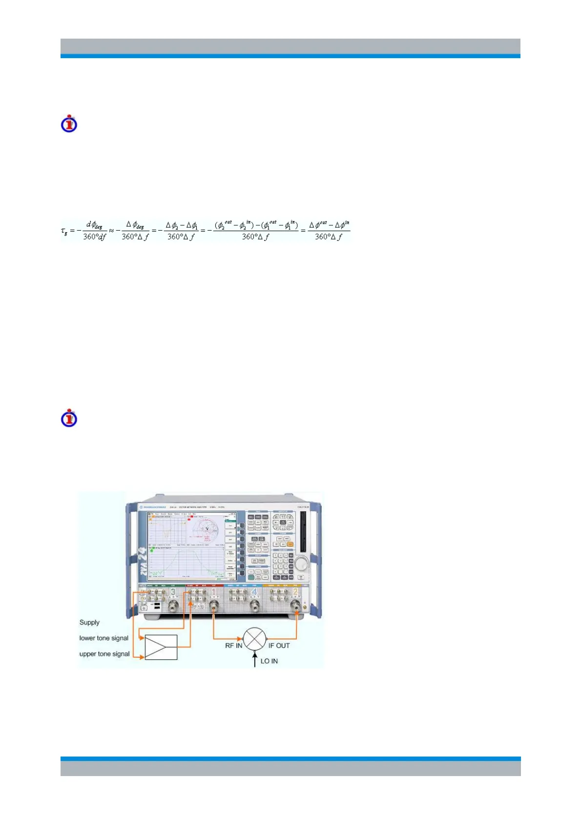
Test Setups with Internal Receiver
The mixer delay measurement requires two independent RF signal sources. The two IF signals can be
measured simultaneously at a single analyzer port. For an R&S ZVA analyzer that is equipped with option
R&S ZVA<frequency>-B16, Direct Generator/Receiver Access, a test setup of the following type is
recommended:
Test setup 1: External combiner
The lower tone signal is generated at port 1, the upper tone is provided by port 3. Both signals are
combined externally and fed to the SOURCE IN connector at port 1.Thus the superimposed signals are