R&S
®
ZVA / R&S
®
ZVB / R&S
®
ZVT GUI Reference
Channel Menu
Operating Manual 1145.1084.12 – 30 414
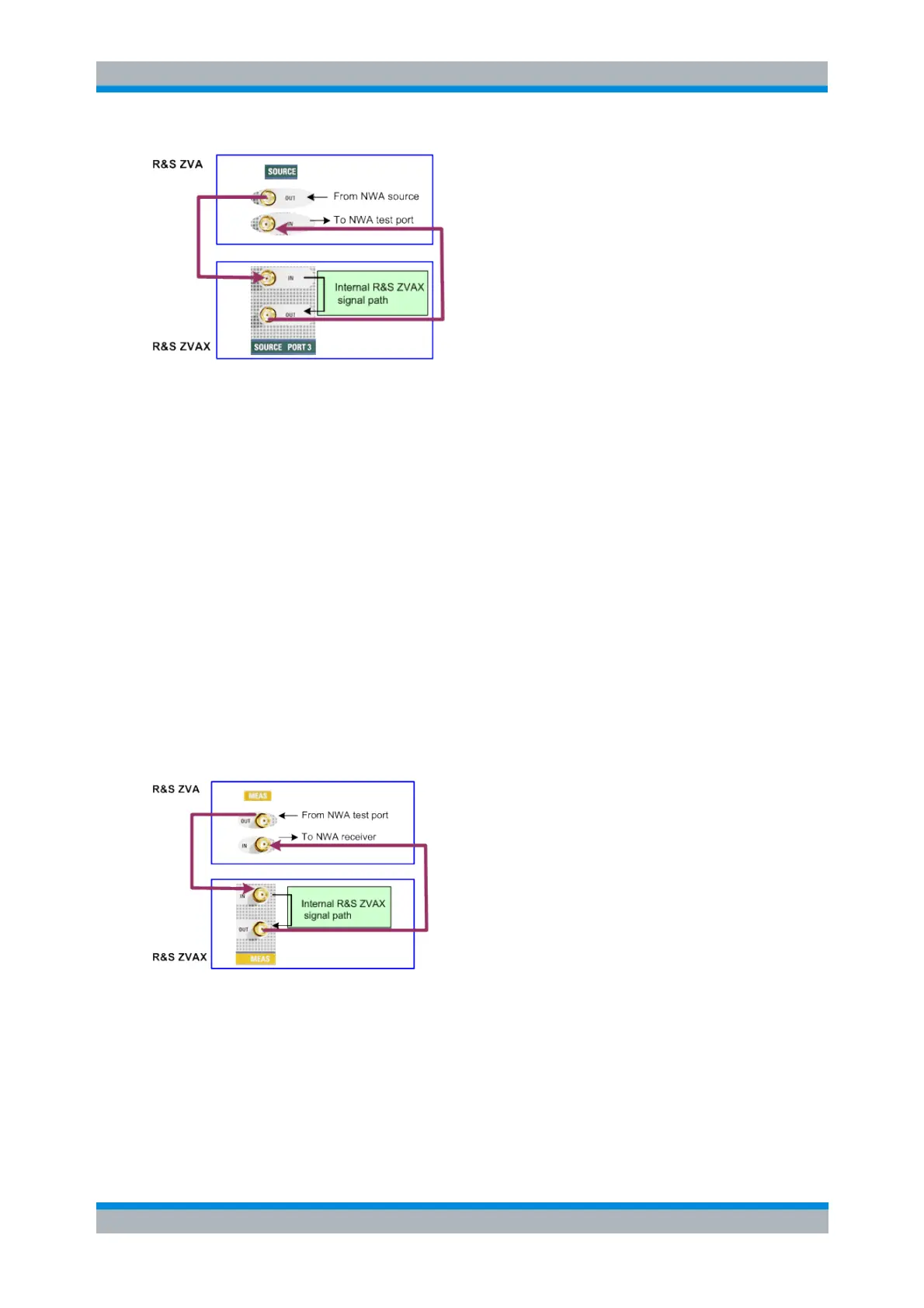
Source path for port 1
The source path for port 1 is analogous to the source path for port 3 described above.
Receiver path for port 2
The received signal from the analyzer test port is fed to the MEAS PORT 2 IN connector of the
Extension Unit. The modified received signal is looped back to the analyzer and fed to the
receiver. The internal R&S ZVAX signal path (green rectangle in the figure below) may contain the
following modules:
A low-noise preamplifier to amplify the signal and reduce the noise figure at the receiver,
in particular for accurate noise figure measurements
A pulse modulator to generate a pulsed source signal
A harmonic filter for very accurate frequency-converting measurements, in particular
harmonics measurements
An external spectrum analyzer connected to the PORT 2 MONITOR connector of the
Extension Unit, providing additional insight into the properties of the modified signal
Each of the modules above may be bypassed or missing. The "empty" source path is a simple
through connection between the MEAS PORT 2 IN and MEAS PORT 2 OUT connectors of the
Extension Unit.
The external connectors are modified if a High Power Coupler is fitted at port 1 or port 2 of the Extension
Unit. Refer to the R&S ZVAX operating manual for details. Please observe the safety instructions in the
R&S ZVAX operating manual.
[SENSe<Ch>:]EUNit:COMBiner[:STATe]
[SENSe<Ch>:]EUNit:HFILter<Path>[:STATe]
[SENSe<Ch>:]EUNit:PMODulator<Path>[:STATe]
[SENSe<Ch>:]EUNit:LNAMplifier[:STATe]