R&S
®
ZVA / R&S
®
ZVB / R&S
®
ZVT GUI Reference
Channel Menu
Operating Manual 1145.1084.12 – 30 417
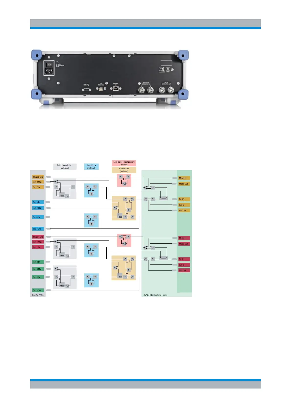
The block diagram below shows a R&S ZVAX-TRM equipped with all available options. It also illustrates
the possible SOURCE, REF and MEAS signal paths, resulting from the available options and the state of
the transfer switches related to a particular building block.
By means of the transfer switches, which are part of each building block, the respective component can be
looped into the RF path or simply bypassed. This corresponds to activating/deactivating the corresponding
module in the ZVAX-TRM Configuration dialog.
ZVAX-TRM Configuration
The ZVAX-TRM Configuration dialog comprises four tabs, providing access to the RF path configuration of
the R&S ZVAX-TRM and to frequently used parameters of related measurements:
RF Path
Pulse Generators
Pulse Modulators
Trigger