IMAGE PROCESSING 26 July 2002
6-24
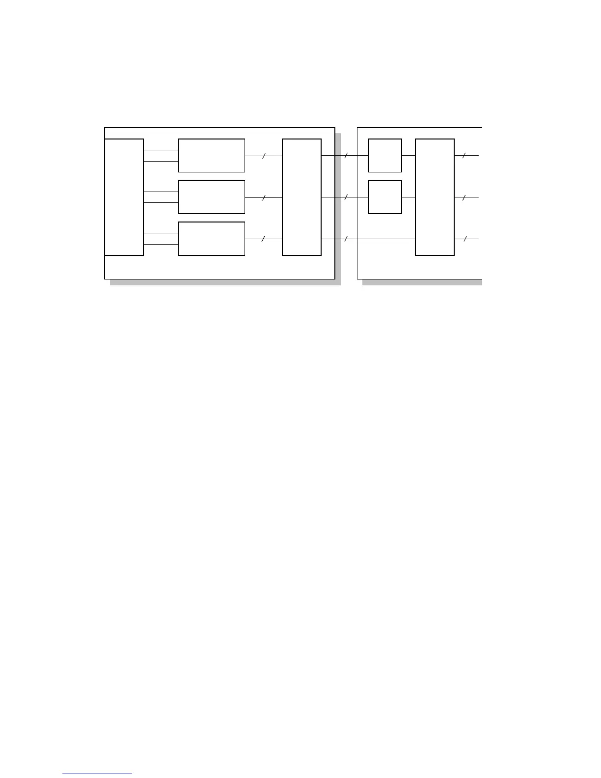
6.6.2 SBU BLOCK DIAGRAM
Signal Processing
1. Signal Amplification
• Odd-pixel and even-pixel RGB analog signals from the CCD are amplified.
2. Signal Composition
• The amplified signals are combined after A/D conversion.
A/D Conversion
• The analog signals (CCD output) are converted to 10-bit (1,024 gradations)
digital signals.
White Level Correction
• A white reference plate is scanned before the original is scanned.
• Data is updated before the original is scanned.
• The differences in the white level across the page, including irregularities in the
CCD and the optical parts across the main scan, are corrected.
Others
The SBU controller exchanges the R and B signals if originals are scanned through
the ARDF.
Analog Amplifier
A/D Converter
CCD
SBU
Analog Amplifier
A/D Converter
Analog Amplifier
A/D Converter
SBU
Controller
R(B)O
E
O
E
O
E
G
B(R)
10 bit
10 bit
10 bit
Field
Memory
Field
Memory
ASIC
BICU
10 bit
10 bit
10 bit
R
G
B
8 bit
8 bit
8 bit
B051D551.WMF
 Loading...