26 July 2002 SERVICE PROGRAM MODE
5-47
Service
Tables
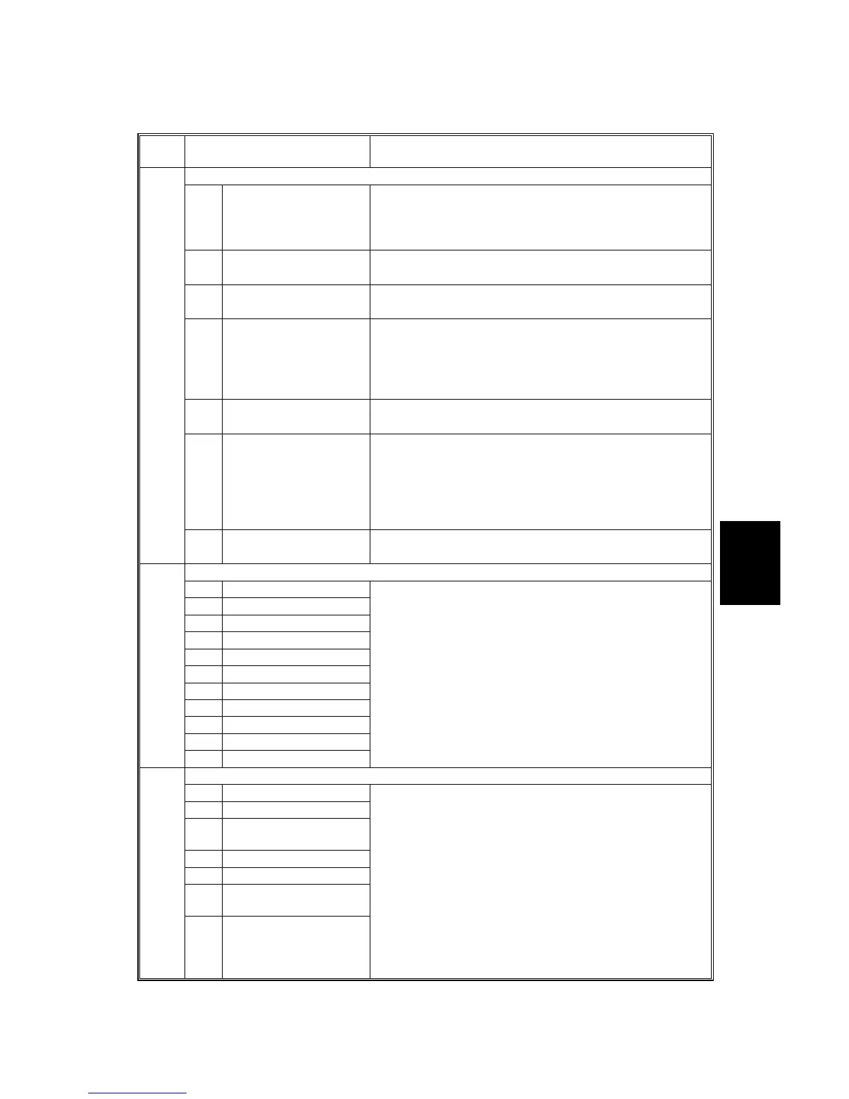
SP6-XXX: (Peripherals)
6
Mode No.
(Class 1, 2, and 3)
Function / [ Setting ]
ADF Adjustment
1 S-to-S Registration Adjusts the side-to-side registration of the optional ADF.
[–5.0 ∼ 5.0 / 0 / 0.1 mm/step]
The main scan registration of the ADF cannot be
adjusted. Adjust the copier registration if necessary.
2
Leading Edge
Registration
Adjusts the sub-scan registration of the optional ADF.
[–5.0 ∼ 5.0 / 0 / 0.1 mm/step]
3 Trailing Edge Erase Adjusts the trail edge erase of the optional ADF.
[–5.0 ∼ 5.0 / 0 / 0.1 mm/step]
4
S-to-S Registration
(Rear)
Adjusts the rear-side side-to-side registration of the
optional ADF.
[–5.0 ∼ 5.0 / 0 / 0.1 mm/step]
The main scan registration of the ADF cannot be
adjusted. Adjust the copier registration if necessary.
5 Sub-san Magnification Adjusts the sub-scan magnification of the optional ADF.
[–5.0 ∼ 5.0 / 0 / 0.1 %/step]
6 Orig. Buckling
Enables/disables original buckling during rear side
scanning. Disable if the customer is scanning fragile
originals.
[0 ∼ 1 / 1 / 1 /step]
• 0: Disabled
• 1: Enabled
006*
7 Buckle Adjustment Adjusts original buckling for rear side scanning.
[–5.0 ∼ 5.0 / 0 / 0.1 mm/step]
DF Input Check
1 Original Set
2 Original Width 1
3 Original Width 2
4 Original Length 1
5 Original Length 2
6 Orig. Trailing Edge
7 Cover Open
8 DF Position
9 Registration
10 Original Exit
007
11 Original Reverse
Displays the signals received from sensors and switches
of the ARDF.
See section 5.1.4
Do not check another item before the result is returned.
DF Output Check
1 Feed Motor (Forward)
2 Feed Motor (Reverse)
3
Trans. Motor
(Forward)
4 Feed Clutch
5 Pick-up Solenoid
6
Junction Gate
Solenoid
008
7 Stamp Solenoid
Switches on each electrical component of the ARDF for
testing.
See section 5.1.5
Do not start to check another item before ending the test
that is in progress.
 Loading...