26 July 2002 SCANNER UNIT
3-3
Replacement
Adjustment
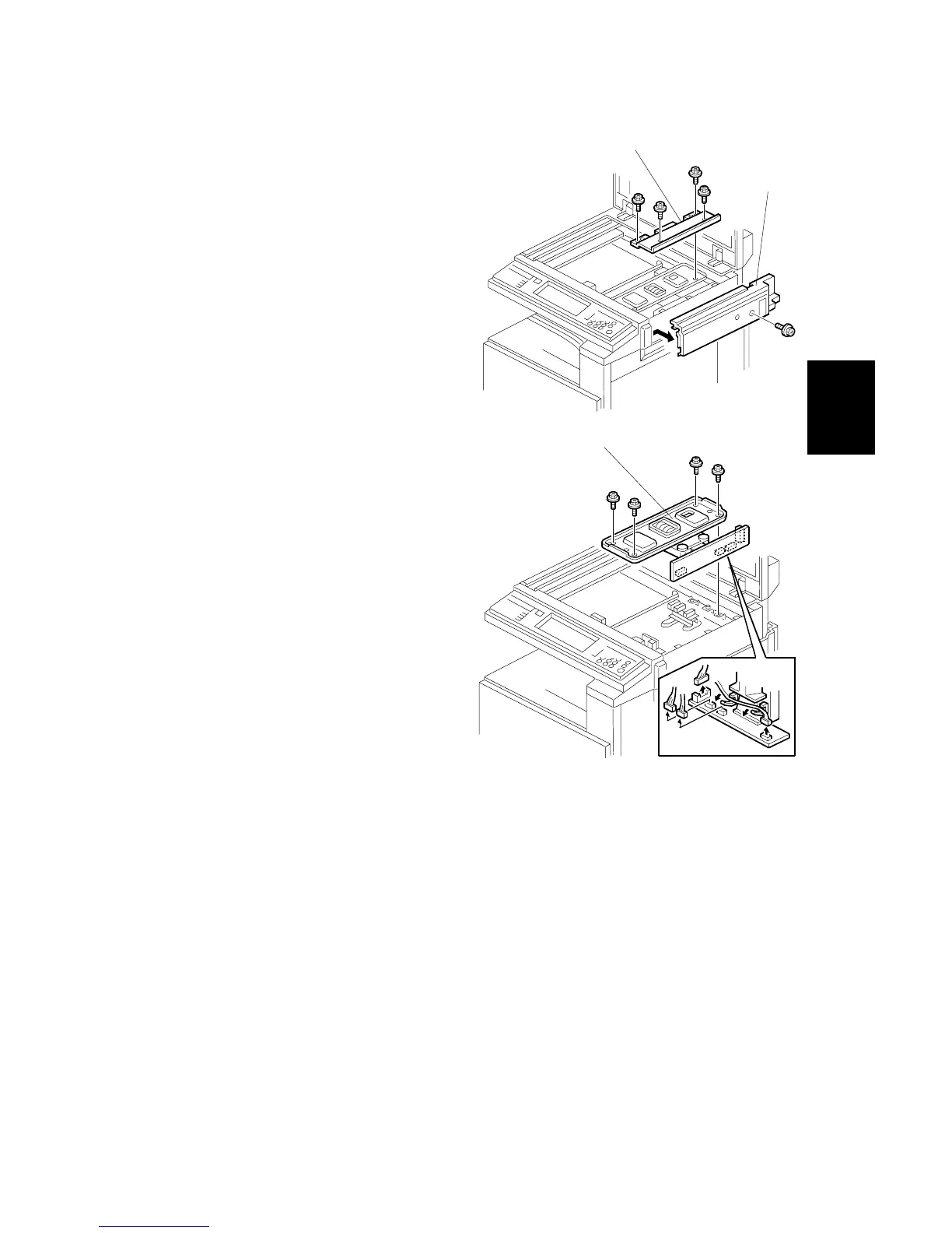
3.3.3 LENS BLOCK ASSEMBLY
1. Exposure glass (☛ 3.3.1)
2. Rear cover (☛ 3.4.2)
3. Scanner right cover [A] (! x 1)
4. Inner cover [B] (! x 4)
5. Lens block assembly [C]
(! x 4, " x 4)
NOTE: Do not remove the paint-
locked screws.
6. After reassembling, input the data
in accordance with the data sheet
included in the spare SBU unit (☛
SP4-540).
Refer to the diagram on the next
page.
• Row No. 1: Numbers 1 to 6 –
please ignore
• Row No. 2: Numbers 7 to 10 –
please store in the following SP
modes
7: SP 4-540-001
8: SP 4-540-002
9: SP 4-540-003
10: SP 4-540-004
• Row No. 3: Numbers 11 to 14 – please store in the following SP modes
11: SP 4-540-021
12: SP 4-540-022
13: SP 4-540-023
14: SP 4-540-024
• Before inputting the number, check whether it is + or – (look at the data
sheet), then input a +ve or –ve number accordingly.
7. Check the registrations (☛ SP4-010/011 Chapter 3, Copy adjustments)
NOTE: After replacing the left scale, adjust the scanner white level (☛ 3.14).
B051R004.WMF
B051R005.WMF
[B]
[C]
[A]
 Loading...