AUTOMATIC TRANSAXLE (M13 ENGINE) 7B1-89
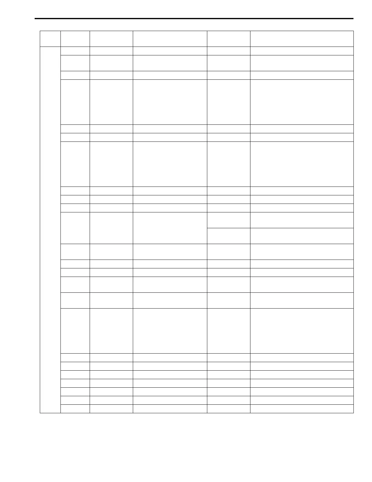
Con-
nector
Te r mi nal
number
Wire color Circuit
Normal
Voltage
Condition
E13
1 BLK Ground 0 – 1 V Ignition switch ON
2 LT GRN/RED
Pressure control solenoid
valve (–)
0.6 – 1.0 V Ignition switch ON
3 ––– –
4 BRN/YEL
Pressure control solenoid
valve (+)
0 – 0.6 V
↑↓
10 – 14 V
(Reference
waveform
No.3)
Engine running at idling.
(Output signal is duty pulse. Duty
ratio varies depending on throttle
valve opening.)
5 WHT/BLU TCC solenoid valve 0 – 1 V Engine running at idling speed.
6 WHT/RED Power source 10 – 14V Ignition switch ON
7WHT
CAN communication line
(Low)
2.5 – 3.6 V
↑↓
1.6 – 2.5 V
(Reference
waveform
No.4)
Engine running at idling with after
warming up.
(CAN communication signal is pulse.
Pulse signal frequency varies
depending on engine condition.)
8 ––– –
9 ––– –
10 ––– –
11 GRN
Transmission fluid temper-
ature sensor (+)
2.9 – 3.1 V
Ignition switch ON, fluid temperature
is 20°C (68°F)
0.3 – 0.5 V
Ignition switch ON, fluid temperature
is 100°C (212°F)
12 BLU/RED
Transmission fluid temper-
ature sensor (–)
0 – 1 V Ignition switch ON
13 ––– –
14 WHT/RED Timing solenoid valve 0 – 1 V Ignition switch ON
15 BLK/YEL
Shift solenoid valve-B
(No.2)
9 – 14 V
Ignition switch ON, select lever in “P”
range
16 BRN
Shift solenoid valve-A
(No.1)
9 – 14 V
Ignition switch ON, select lever in “P”
range
17 RED
CAN communication line
(High)
2.5 – 3.6 V
↑↓
1.6 – 2.5 V
(Reference
waveform
No.4)
Engine running at idling with after
warming up.
(CAN communication signal is pulse.
Pulse signal frequency varies
depending on engine condition.)
18 ––– –
19 ––– –
20 ––– –
21 ––– –
22 ––– –
23 BLK Ground 0 – 1 V Ignition switch ON
24 WHT/BLU Power source for back-up 10 – 14 V Constantly