111
Smart Camera / Vision-Sensor / 1D-/2D-Code-Scanner / OCR Reader
11.9.2. Settings
Image Area
Detected clusters appear in the image area with a light blue frame.
Property
The following settings/results are displayed:
Process-Time [ms] Sensor processing time for the module
Module State Error codes to give support in error diagnosis (see section
18.5)
Cluster True Count The number of objects in the image area which has been
detected using the corresponding settings is displayed.
Input Image Selection of the image input
Cluster Size Min The minimum number of adjoining white pixels can be speci-
fied, so that the respective area is counted as a cluster.
Cluster Size Max The maximum number of adjoining white pixels can be speci-
fied, so that the respective area is still counted as a cluster.
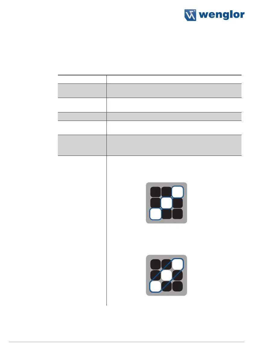
Cluster Gap
Connected 4
Only directly adjacent white pixels
(above, below to the left and to the right)
are interpreted as belonging together to
a single object.
Three clusters are counted in the example.
Connected 8
Pixels joined by their corners are also
interpreted as belonging together to a
single object.
Only one cluster is counted in the example.