EN
170
Software Module
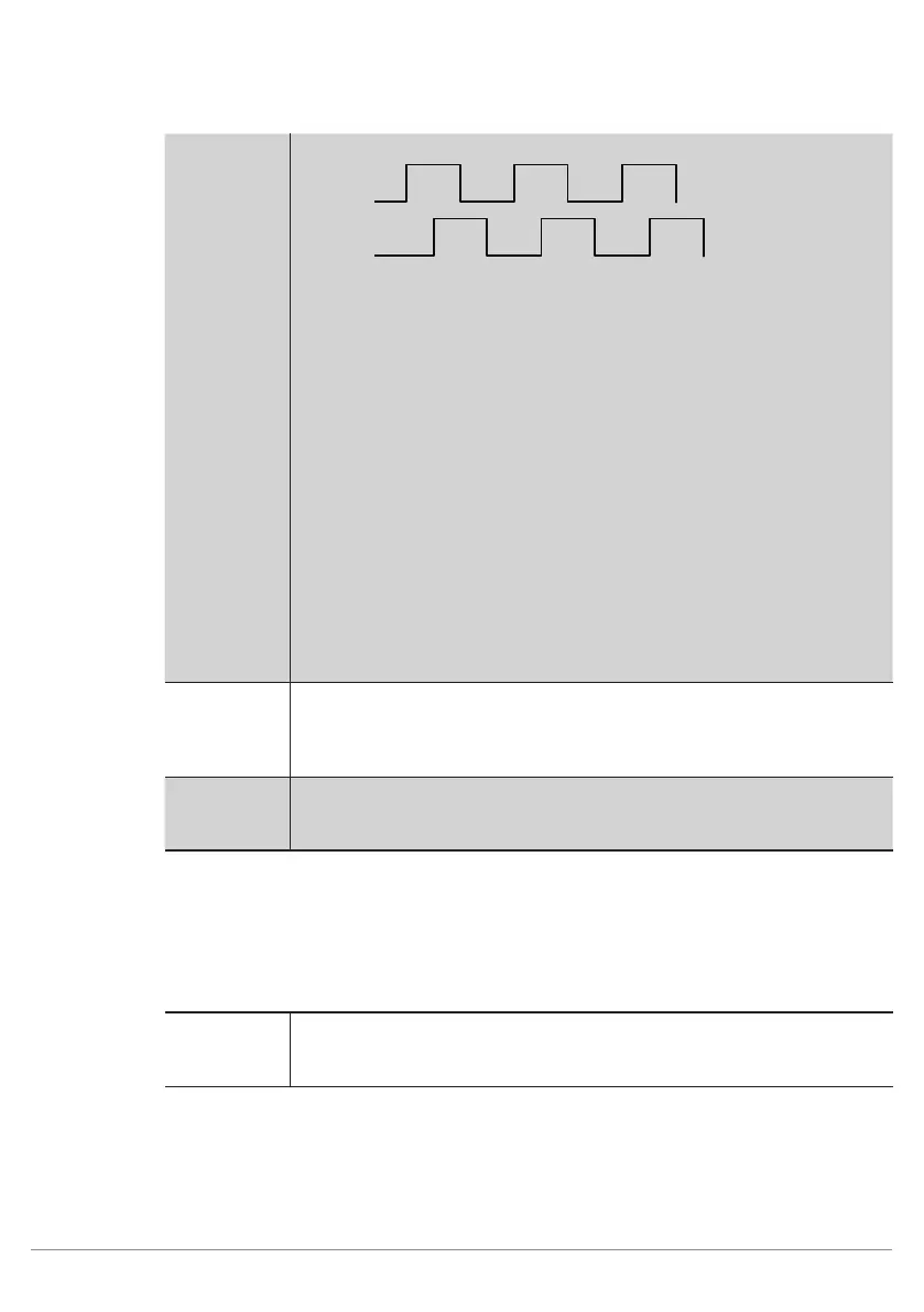
Channel A
Channel B
These two signals have to be connected to two sensor
pins, regardless of order. The selected pins have to be
connected to Input Quadrature in weQube software.
Furthermore, the timing unit has to be set to quadrature
pulses under IO timings (see section 11.21.3.1). All IO
timings are then displayed in pulses instead of millisec-
onds.
Example: A further pin can now be used as a hardware
trigger input and the number of pulses required to cause
image recording after the hardware trigger signal has oc-
curred can be entered to the trigger delay settings. You
can also set up an event delay in order to specify after
how many pulses certain outputs will be switched.
Input Project
Selection
The input is used to change projects and reacts to the
project change pulse sequence. Further information is
included in section 12.
Output Mode The polarity of the output is specified.
• PNP
• NPN
• Push-Pull
Event Link The output can be linked to one of the four 4 event delays. As a result, the
output is switched with a delay amounting to the time selected under IO
timings (see section 11.21.3.1).
11.21.3.3. Error Handling
This setting can be used to set performance of the properties when a linked event demonstrates an error status.
Property
Individual texts can be displayed:
Substitute
BOOL
Types by
If this checkbox has been activated, all properties of the Boolean type are
replaced by the active value, if the linked file type demonstrates an error.