139
Smart Camera / Vision-Sensor / 1D-/2D-Code-Scanner / OCR Reader
11.13. Module Image Comparison
11.13.1. Overview
Objective
Objects can be compared with the stored Reference Image and any deviations can be
reliably detected with the help of the Module Image Comparison.
Prerequisites
1. Sensor is correctly connected (see section 5.5)
2. Connection has been established from the sensor to the software
(see section 10.1.1)
3. Region of interest is specified (see section 11.5)
Procedure
First of all, one or more images (see Teach Image Count) of good parts will be used to
calculate the Reference Image.
Then the Input Image will be compared pixel by pixel with the Reference Image. If the
deviation of a pixel is bigger than the value of the pixel in the Threshold Image, the pixel
will be marked as an error (white) in the Output Image. If the deviation is smaller than
the value of pixel in the Threshold Image, the pixel of the Input Image is marked as an
accepted (black) value in the Output Image (only visible in Advanced Mode).
The errors are also visible if you click in the Module Image Comparison itself. To make
them more visible, they are marked red.
11.13.2. Settings
Image Area
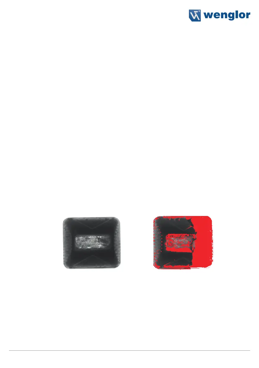
Deviations from the reference object are displayed as red pixels in the image area.
Reference Object Displayed Deviation from the
Reference Object


 To Next Page