Crankcase
7-63
• Make sure that the protrusions “a” on the
connecting rod and connecting rod caps “1”
are facing toward the flywheel magneto end
of the crankshaft.
• In the second tightening stage for the con-
necting rod bolts “2”, mark the connecting rod
bolts and connecting rod cap with paint
marks “b”, and then
tighten the connecting
rod bolts 60 from the marks on the connect-
ing rod cap.
• After tightening the conn
ecting rod bolts “2”,
make sure that the crankshaft turns smooth-
ly.
9. Install:
• Dow
el pin
10. Install:
• Crankshaft journal bearing
• Thrust bearing
• O-ring
• Crankcase
• Crankcase bolt (M10)
• Crankcase bolt (M8)
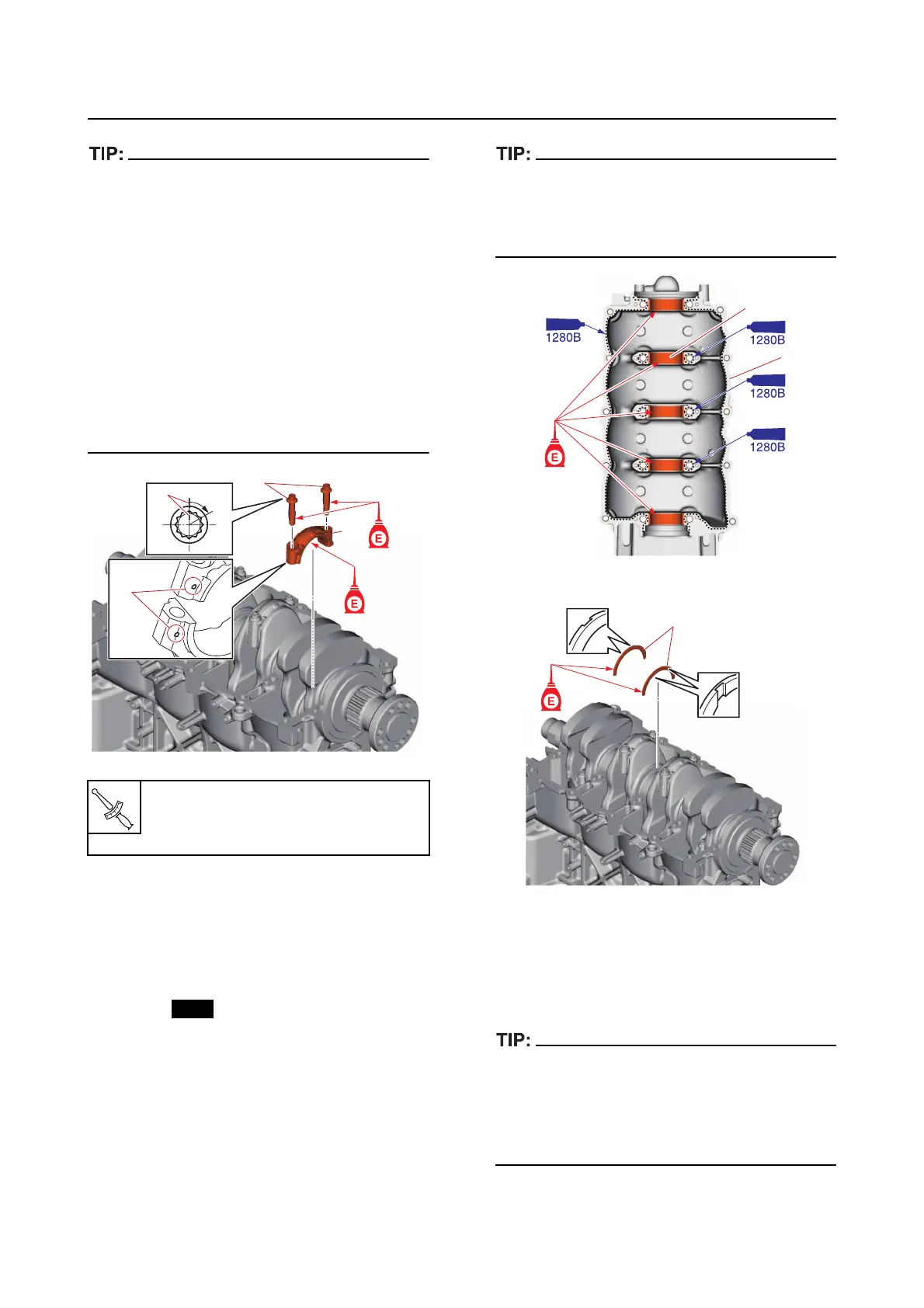
a. Install the crankshaft journal bearings
“1” onto
the crankcase “2”.
b. Apply a thin, even layer of sealant onto
the mating surface of the crankcase.
• Install the crankshaft journal bearings “1” in
their original positions.
• Do not apply any sealant to the crankshaft
journal bearings “1”.
c. Install the thrust bearings “1”.
d. Install a new O-ring “1” and the crank-
case “2”, and then tighten the crank-
case bolts (M10) “3” to the specified
torque
s in 2 stages and in the order
[1], [2], and so on.
In the second tightening stage for the crank-
case bolts (M10) “3”, mark the crankcase bolts
(M10)
and the crankcase “2” with identification
marks “a”, and then tighten the bolts 60 from
the marks on the crankcase.
Connecting rod bolt “2”
1st: 13 N·m (1.3 kgf·m, 9.6 lb·ft)
2nd: 60
1