12-33
IM DLM4038-02EN
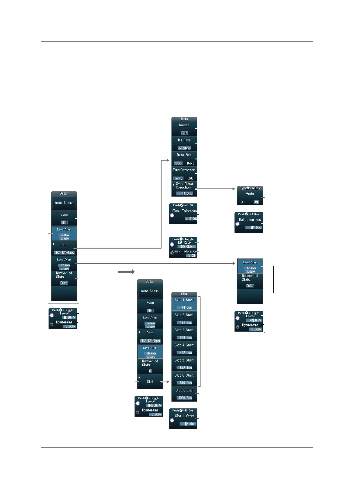
Manual Setup
After running auto setup, you can change the following settings and display decoded results.
• Sync signal source
• Data frame source
Bit rate, data length, error detection method, sync noise rejection, clock tolerance
• Number of slots
Set the time range of each slot (when the number of slots is set to a number from 1 to 6)
• Level used to detect source states
• Hysteresis
Set the number
of slots.
(Auto, 1 to 6)
Set the bit rate.
(125kbps, 189kbps, User Define)
Set the level and
hysteresis of the sync
signal.
Set the level and
hysteresis of the
data frame source.
• Level used to detect
sync signal states
• Level used to
detect data frame
source states.
Set the bit rate.
Set the clock tolerance.
Set the sync signal.
CH1 to CH8, Math1 to Math4, X
Set the data length (10bit, 16bit).
Set the error detection method (Parity, CRC)
1
Turns on or off the
rejection mode
Set the rejection
end.
Set the clock
tolerance.
Select the last slot for setting the end position.
Set the data frame source.
(CH1 to CH8, Math1 to Math4)
When the bit rate is set
to User Define
• Hysteresis
• Hysteresis
Set the sync noise rejection.
2
When the number of slots is set to a
number from 1 to 6
(Example When the number
of slots is set to 6)
Set the time range
of each slot.
Set the start position of each slot and
the end position of the last slot.
Select the slot for setting the start position.
1 When the data length is 16 bit, the error detection method is fixed to CRC.
2 When the sync signal source is X, the sync noise rejection is set to OFF, and the sync noise rejection menu does not appear.
12.7 Analyzing and Searching PSI5 Airbag Signals (Option)
 Loading...


