7-1
IM DLM4038-02EN
Chapter 7 FFT
7.1 Displaying FFT Waveforms
This section explains the following settings (which are used when performing FFT analysis).
• FFT waveform display
• Analysis source waveform
• FFT conditions
• Analysis range
• Vertical and horizontal scale values
• FFT points
► “FFT” in the Features Guide
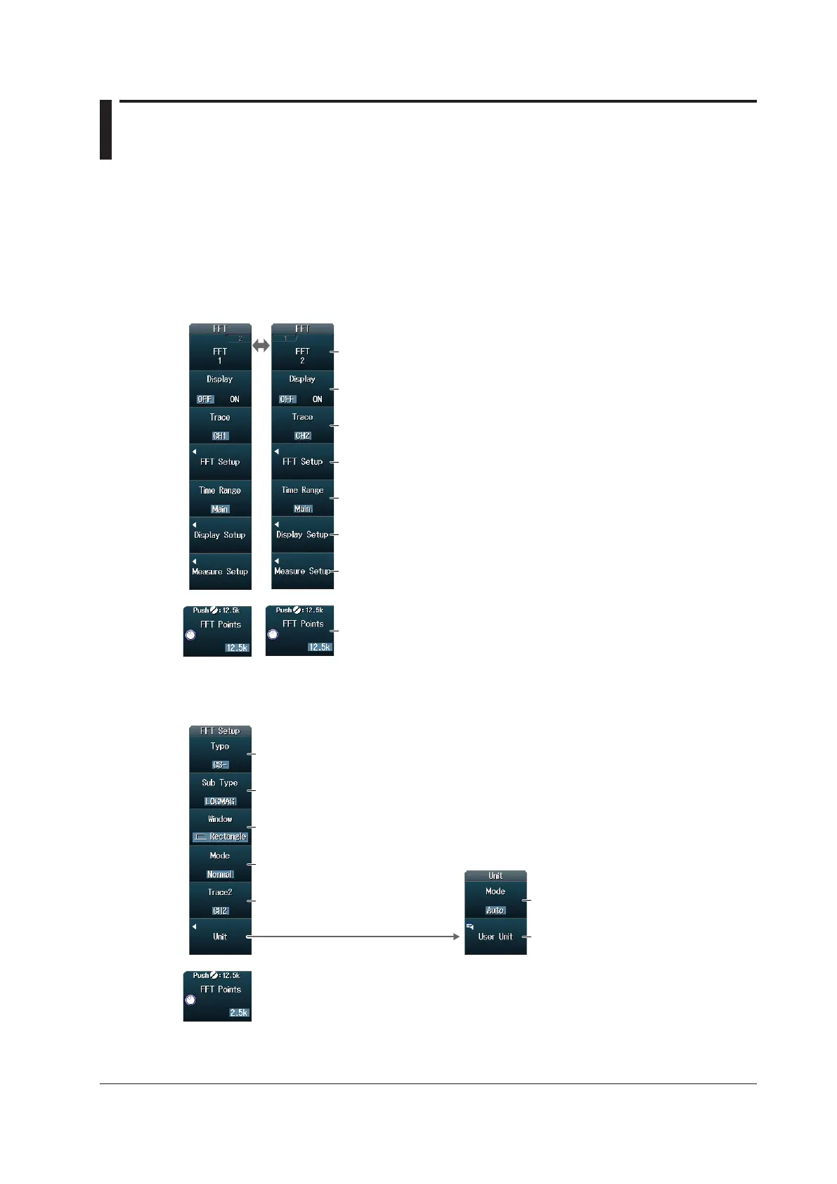
FFT Menu
Press SHIFT+MATH/REF (FFT) to display the following menu.
Set the number of FFT points.
Set the vertical and horizontal scale values.
Set the analysis range (Main, Zoom1, Zoom2).
Configure the FFT conditions.
Set the analysis source waveform (CH1 to CH8, Math1 to Math4).
Turn the FFT waveform display on or off.
Select whether to set FFT1 or FFT2.
Configure FFT waveform measurement.
► section 7.2
Setting FFT Conditions (FFT Setup)
Press the FFT Setup soft key to display the following menu.
Set the unit.
Set the unit type (Auto, User Define).
Set the user-defined unit
using up to 4 characters.
Set the time window (Rectangle, Hanning, Flattop).
Set the waveform display method
(Normal, Max Hold, Average).
Set the spectrum type
(LS−, RS−, PS−, PSD−, CS−, TF−, CH−).
1
Set the spectrum sub type
(MAG, LOGMAG, PHASE, REAL,
IMAG).
1, 2
Set the analysis source waveform
(CH1 to CH8, Math1 to Math4).
3
1 This is available on models with the user-defined computation option.
2 PHASE, REAL, and IMAG can be specified when Type is set to LS‒, CS‒, or TF‒.
3 Can be specified on models with the user-defined computation option when Type is set to CS‒, TF‒, or CH‒.

 Loading...


