14-10
IM DLM4038-02EN
14.6 Measuring Power
This section explains the following settings (which are used when measuring power).
• Turning power measurement on and off
• Probe
• Measurement conditions
Measurement items, reference levels for time measurements, measurement location indicator,
measurement source window, and measurement time range
► “Power Measurement (Power Measurement)” in the Features Guide
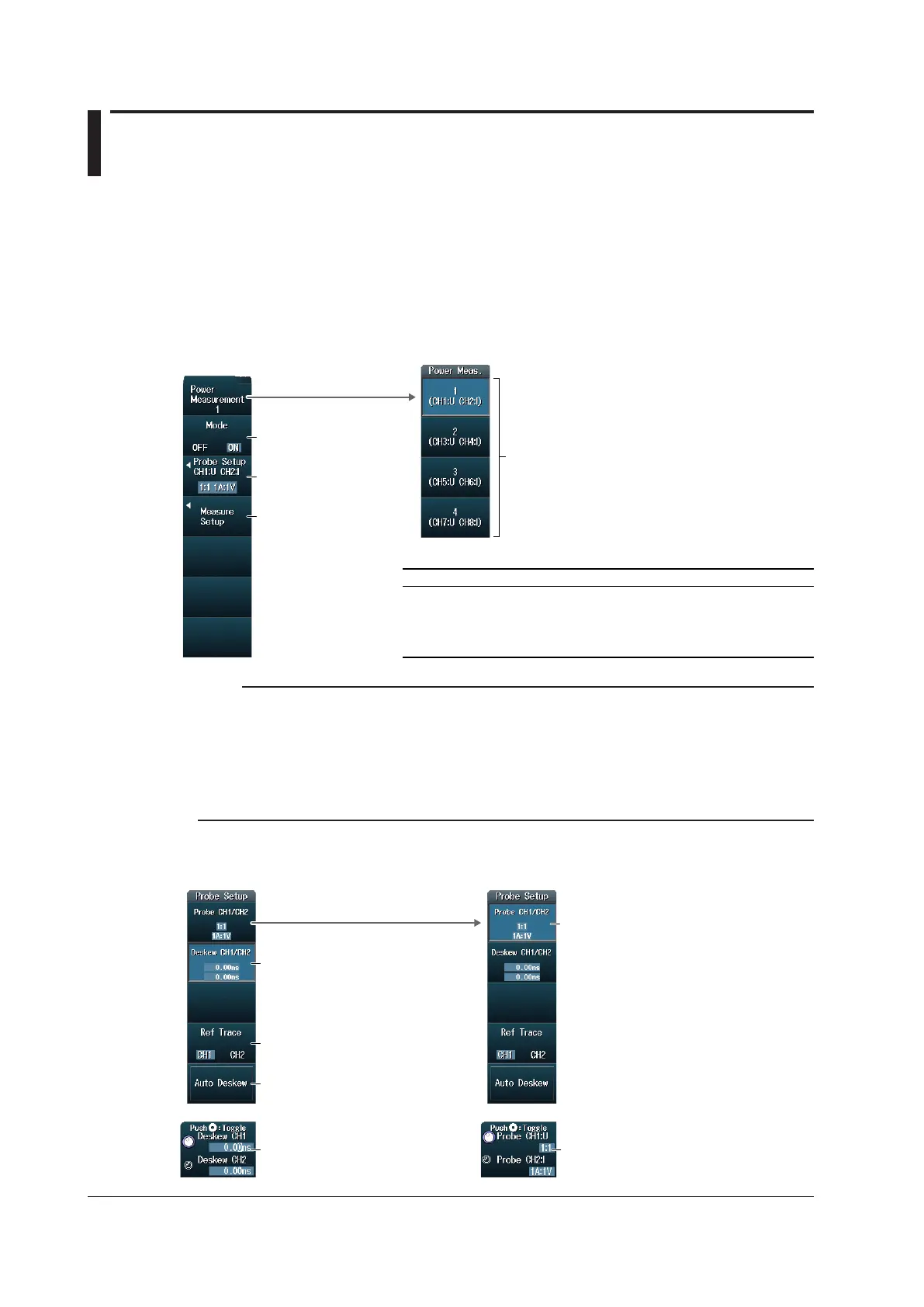
ANALYSIS Power Measurement Menu
Press ANALYSIS and then the Power Measurement soft key to display the following menu.
Turns power
measurement on and off
Set the measurement
conditions.
Select which power measurement to
set (Power Measurement1 to Power
Measurement4).
Configure the probe.
Power Measurement Voltage Input Channel Current Input Channel
Power Measurement1 CH1 CH2
Power Measurement2 CH3 CH4
Power Measurement3 CH5 CH6
Power Measurement4 CH7 CH8
The voltage and current input channels are fixed as follows:
Note
• For input channels that are assigned to power measurement and whose mode is set to ON, the following
standard waveform parameters cannot be set. Because the measurement items of power measurement
are the same as the following standard waveform parameters, the power measurement values are used
in place of waveform parameters.
Max, Min, P-P, Rms, Mean, Sdev, Avg Freq
• If any of the power measurements is set to ON, cycle mode of the standard waveform parameters is set
to OFF.
Configuring the Probe (Probe Setup)
Press the Probe Setup soft key to display the following menu.
Set the probe attenuation and
voltage-to-current conversion ratio
(using the jog shuttle).
Set the probe attenuation and
voltage-to-current conversion ratio.
Set each channel’s deskew value
(using the jog shuttle).
Set the reference trace.
Executes auto deskewing
Set each channel’s deskew value.
 Loading...


