2-13
IM DLM4038-02EN
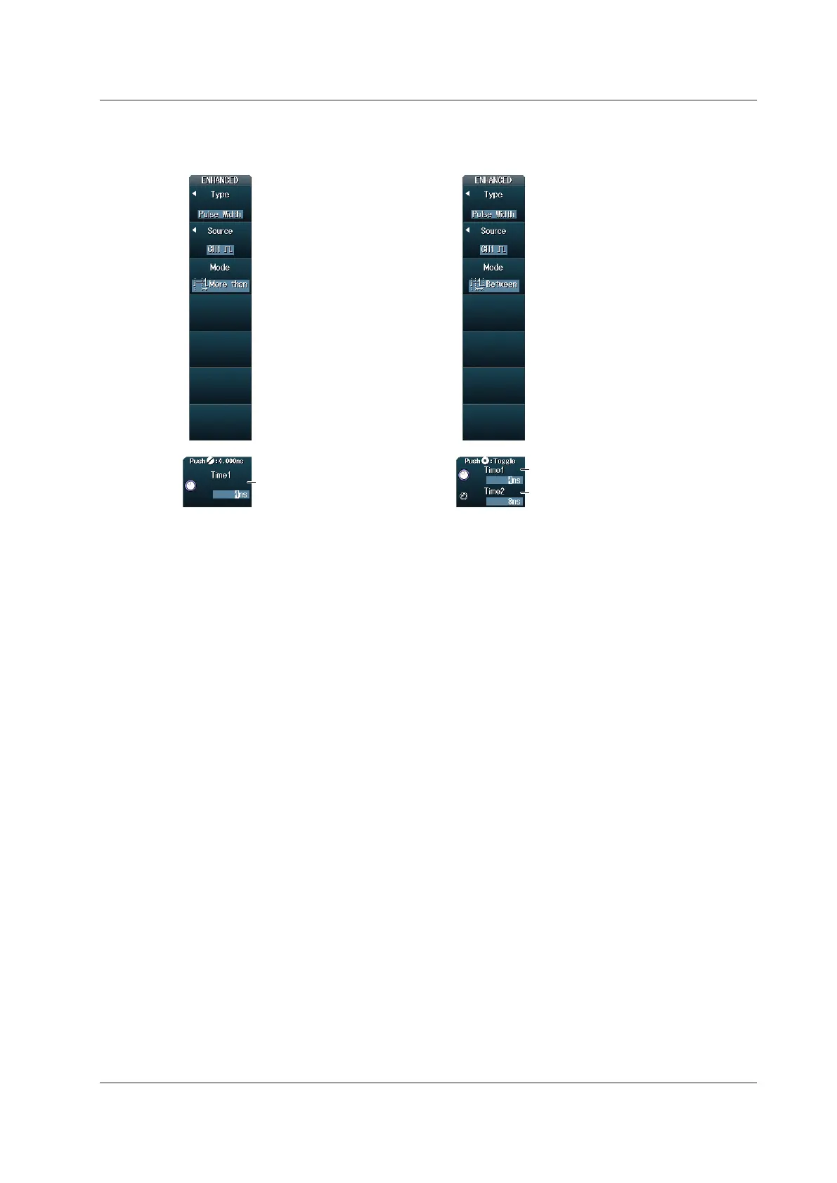
Setting the Reference Times (Time1 and Time2)
When the Time Width Mode Is More
than, Less than, or TimeOut
When the Time Width Mode is
Between or OutOfRange
Set reference time Time1.
Set reference time Time1.
Set reference time Time2.
2.7 Triggering on Pulse Width
 Loading...


