P1086708-001 ZXP Series 9 Card Printer Service Manual 319
Replacement Procedures for the Printer
Procedures: Power Supply (24V, 350W)
Tests and Adjustments
Step 1. Ensure the Printer is fully assembled, except for the covers.
Step 2. Install the color ribbon, transfer lm, and loaded input hopper.
Step 3. Ensure the power switch is in the off position.
Step 4. Connect AC to the printer.
Electric Shock • Do not touch the power supply board or the main PCBA. Use extreme
caution when working near exposed terminals on the power supply.
Step 5. Turn power ON.
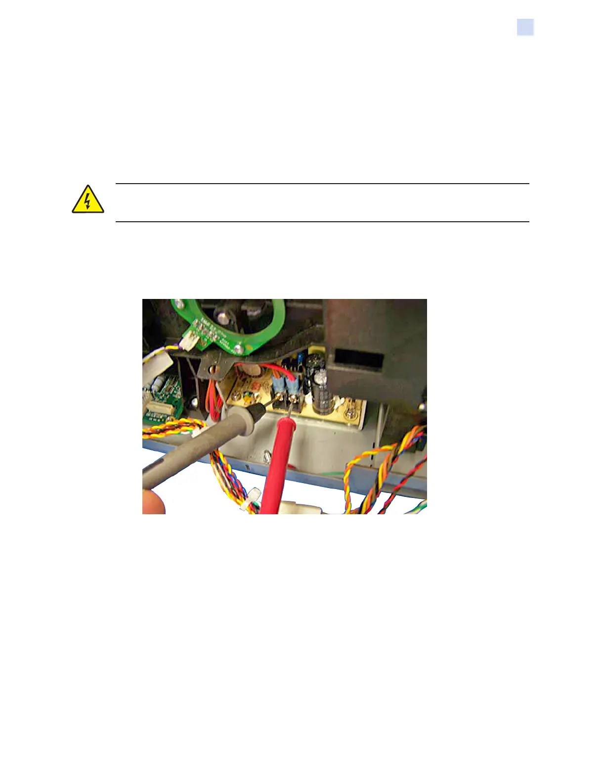
Step 6. With a multimeter in the VDC mode, attach the negative black probe to the brown-
wire terminal; and attach the positive red probe to the red-wire terminal (both
terminals circled below).
Step 7. With a small at-blade screwdriver, adjust the pot screw (arrow above) until the
voltage reads 24 (± 0.2) VDC on the multimeter. Note that turning the pot screw
clockwise increases the voltage and vice versa.
 Loading...