Section 9 Maintenance
9-8
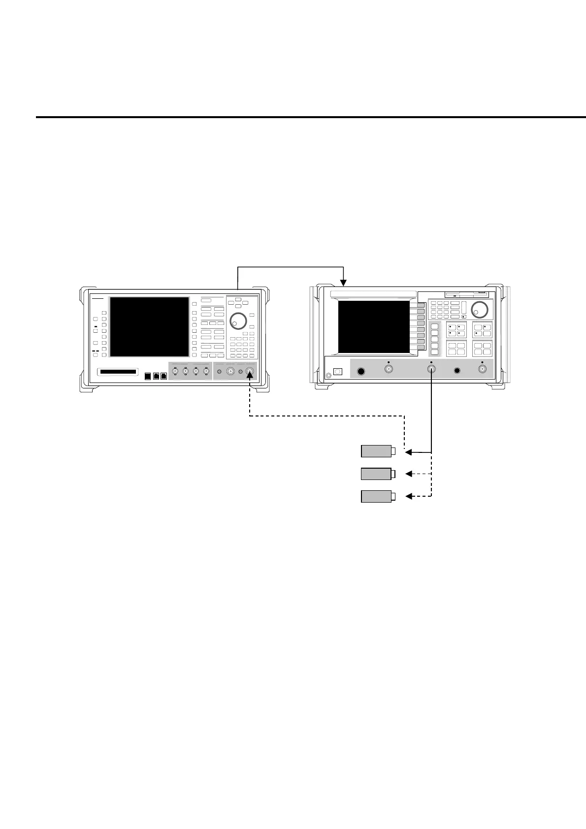
(2) Setup
Connect the equipment as shown in Fig. 9-1-5-1.
Note:
Confirm that the MT8820A RF signal output connector is set to the Main in-
put/output connector. Settings for RF signal output connector can be check-
ed in RF Output on the System Configuration screen.
10 MHz
Ref Output
MS4622A Network Analyzer
nritsu
MT8820A
MT8820A
10 MHz
Ref Input
Anritsu
■
MS4622A
N-type cable
Open Termination
Short Termination
Load Termination
50
Ω
, N-type calibration kit (3753)
Fig. 9-1-5-1 Main input/output connector setup for VSWR value test
(3) Test method
[Procedure]
1. Connect the N-type cable to the network analyzer for connecting with the
MT8820A.
2. Set the start frequency of the network analyzer to 30 MHz and stop fre-
quency to 3 GHz.
3. At the top of N-type cable, perform calibration using Open, Short and
Load termination.
4. Connect N-type cable to the Main1 Input/Output connector of MT8820A.
5. Set the MT8820A reference level (input level) to -65 dBm. To set the
reference level, refer to the operation manual for the measurement soft-
ware.
6. Perform VSWR measurement, then check if the specification is satisfied.