Section 2 Setup
2-14
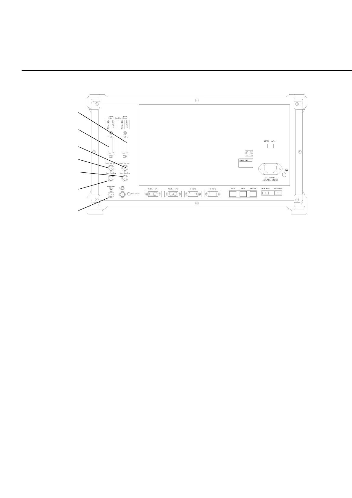
2.1.3 Rear panel
1
2
3
4
5
6
7
Fig. 2-1-3-1 Rear panel (1)
1. GPIB-1 GPIB connector 1
Remote control connector for Phone 1 through GPIB
2. GPIB-2 GPIB connector 2
Currently not available.
3. Event Trig Out-1 Trigger output connector 1
BNC connector for outputting the event timing to external device allocated to
Phone 1.
4. Event Trig Out-2 Trigger output connector 2
Currently not available.
5. Event Trig In-1 Trigger input connector 1
BNC connector for inputting trigger signal from external device and performing
transmission measurement on Phone 1 in synchronization with the external de-
vice.
6. Event Trig In-2 Trigger input connector 2
Currently not available.
7. 10 MHz/13 MHz Ref In Reference signal input connector
BNC connector for inputting an external reference signal. The frequency lock
range is ±1 ppm and the input level range is 2 to 5 Vpp.