9.1 Performance Test
9-13
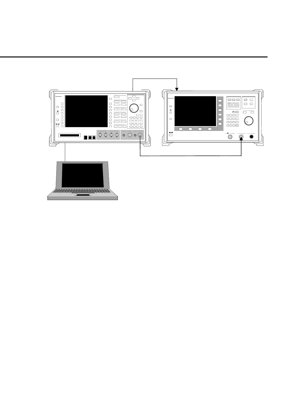
Fig. 9-1-8-2 is a setup example for the output level accuracy test.
Ref In
ut
10 MHz
Buff Out
ut
ML2530A receiver for calibration
MT8820A
PC
Fig. 9-1-8-2 Setting up for the level accuracy test of RF signal generator
Setup the PC to enable control of the MT8820A via GPIB interface.
Note:
Confirm that the MT8820A RF signal output connector (Main or AUX) of
measuring object. Setting for RF signal output connector can be checked in
RF Output on the System Configuration screen.
Note:
Perform the tests (3) and (4) at the same temperature setting.
(3) Frequency characteristics test
[Procedure]
1. Setup the equipment as shown in Fig. 9-1-8-1.
2. Set MT8820A to the non-modulation CW output (command: MOD OFF)
through GPIB control from PC.
3. Perform sensor calibration (for zero point and sensitivity) of the power
sensor.
4. Execute Full Calibration of MT8820A.
5. Connect the power sensor directly to the MT8820A Main1 Input/Output
connector.
6. Set MT8820A output level to −10 dBm.