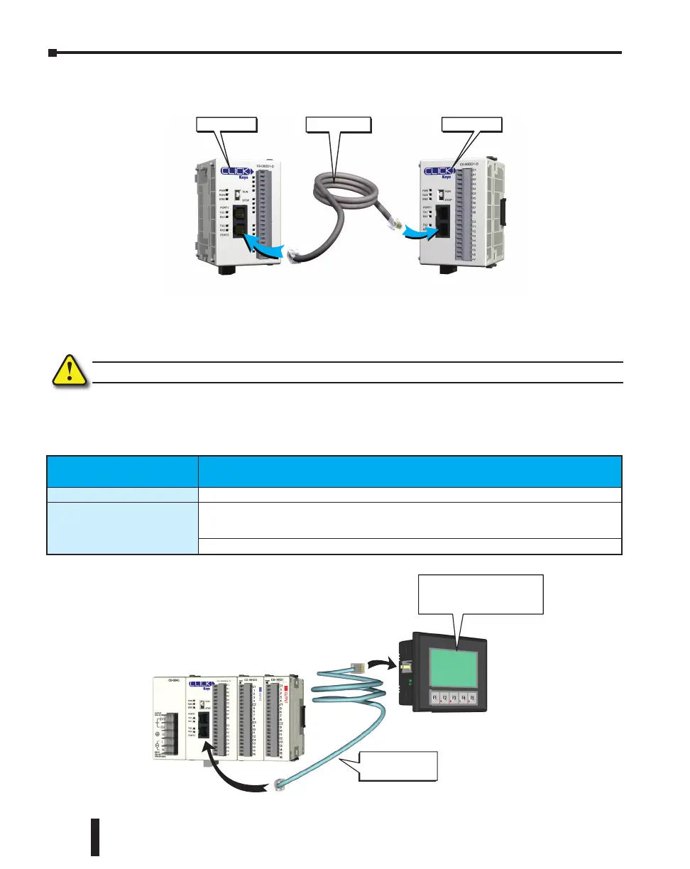
Case 2: Connect Com Port 1 or 2 to another CLICK PLC
You can use cable D0-CBL.
In this configuration, one of the CLICK PLC units needs to be the network master and the
other is the network slave. Connect the D0-CBL on Com Port 2 on the master PLC unit side.
WARNING: The ZL-RJ12-CBL-2 cable cannot be used for this purpose.
Case 3: Connect Com Port 1 or 2 to a C-more or C-more Micro-Graphic panel
Please use the following cables to make your connections.
CLICK PLC CLICK PLC
D0-CBL Cable
C-more Graphic Panel Cable Part Number
C-more Touch panels
EA-2CBL (3m) or OP-2CBL (2m)
C-more Micro-Graphic
Panels
DV-1000CBL if the panel receives 5VDC power from the CLICK PLC com port. (Monochrome
panels only; color panels must be powered from a separate 24VDC power source. Please refer
to the note on page 4-6 for details.)
EA-2CBL (3m) or OP-2CBL (2m) if the panel receives 24VDC power from other source.
Port 1
Port 1 or 2
DV-1000CBL
serial cable
C-more Micro-Graphic
Panel (Monochrome
models only)
CLICK PLC Hardware User Manual, 6th Edition, Rev. F – C0-USER-M
4–14
Chapter 4: PLC Communications

 Loading...