14-24 BE1-951 BESTCOMS Software 9328900990 Rev L
VT Monitor (Fuse Loss Block Logic)
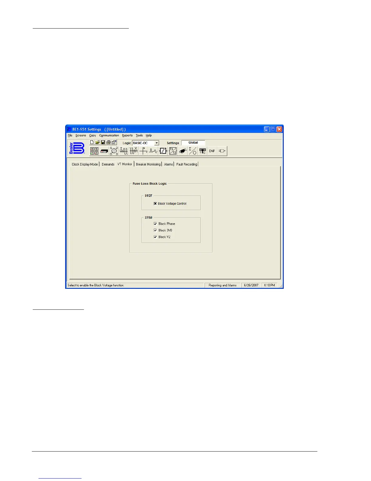
Fuse Loss Block Logic (
Figure 14-32) can prevent misoperation on loss of sensing voltage. This can be
applied on both the 51/27 and 27/59 functions.
When the 51/27 function is set for control and a 60FL condition is detected, the phase overcurrent
elements will be disabled if you place an x in the 51/27 Block Voltage Control field by clicking in the field.
If the 51/27 function is set for restraint and a 60FL condition is detected, the phase overcurrent elements
will remain enabled and the pickup setting is not adjusted from 100% of the setting.
If the 27/59, Block Phase is enabled with a check mark in the field and a 60FL condition is detected, all
functions that use the phase voltage are blocked. If the 27/59, Block 3V0 is enabled with a check mark in
the field and a 60FL condition is detected, all functions that use the auxiliary over/undervoltage (27x/59X)
functions with Mode 2 selected are blocked. If the 27/59, Block V2 is enabled with a check mark in the
field and a 60FL condition is detected, all functions that use the negative-sequence voltage are blocked.
Figure 14-32. Reporting and Alarms Screen, VT Monitor Tab
Breaker Monitoring
Each time the breaker trips, the breaker duty monitor updates two sets of registers for each pole of the
breaker. This function selects which of the two sets of duty registers are reported and monitored, sets the
existing values, and programs the function logic.
Use the Breaker Duty Monitoring Exponent pull-down menu (
Figure 14-33) to select the exponent in the
range of 1 to 3. Click in the field for 100% Duty Maximum and set the value. Logic settings for the Block
Accumulation Logic can be made by clicking on the logic button and, with your custom logic selected,
select the block accumulation logic.
Because the relay is completely programmable, it is necessary to program which logic variable monitors
breaker status (how the relay knows when the breaker is closed). Set the Breaker Status Logic by clicking
on the Logic button and with your custom logic selected, select the control logic.
Three breaker alarm points are programmable for checking breaker monitoring functions. Each alarm
point can be programmed to monitor any of the three breaker monitoring functions or all three alarm
points can be programmed to monitor one function and alarm at various threshold levels. Use the pull-
down menu for Breaker Alarms - Point 1 and select the preferred breaker monitoring mode (function).
With the Mode set, the Threshold field is viable and has a zero threshold. Use the keyboard to enter the
threshold value or the appropriate UP or DOWN arrow buttons. Repeat the procedure for Breaker Alarms
- Points 2 and 3. If desired, select the Trigger Oscillographic Record box to create an oscillographic
record.