Operation C 2
ekrPro Com
60
web guide controller EDV-No.: MD.191.01.05/1.6.x Chapter: C 2
with analog sensors Date: 23.11.2007 Page: 1/19
C 2 Operation
C 2.1 General information
C 2.1.1 Graphics display
The various operating statuses are displayed by the graphics
display.
Use the vertical arrow keys to change between the different
displays in normal control mode.
The number of displays varies between one and four, depending
on whether a sensor adjustment unit and/or sensor 3 is
interconnected or not.
Information for the assigned operating mode is shown in the
separate displays and their significances are explained in the
following.
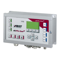
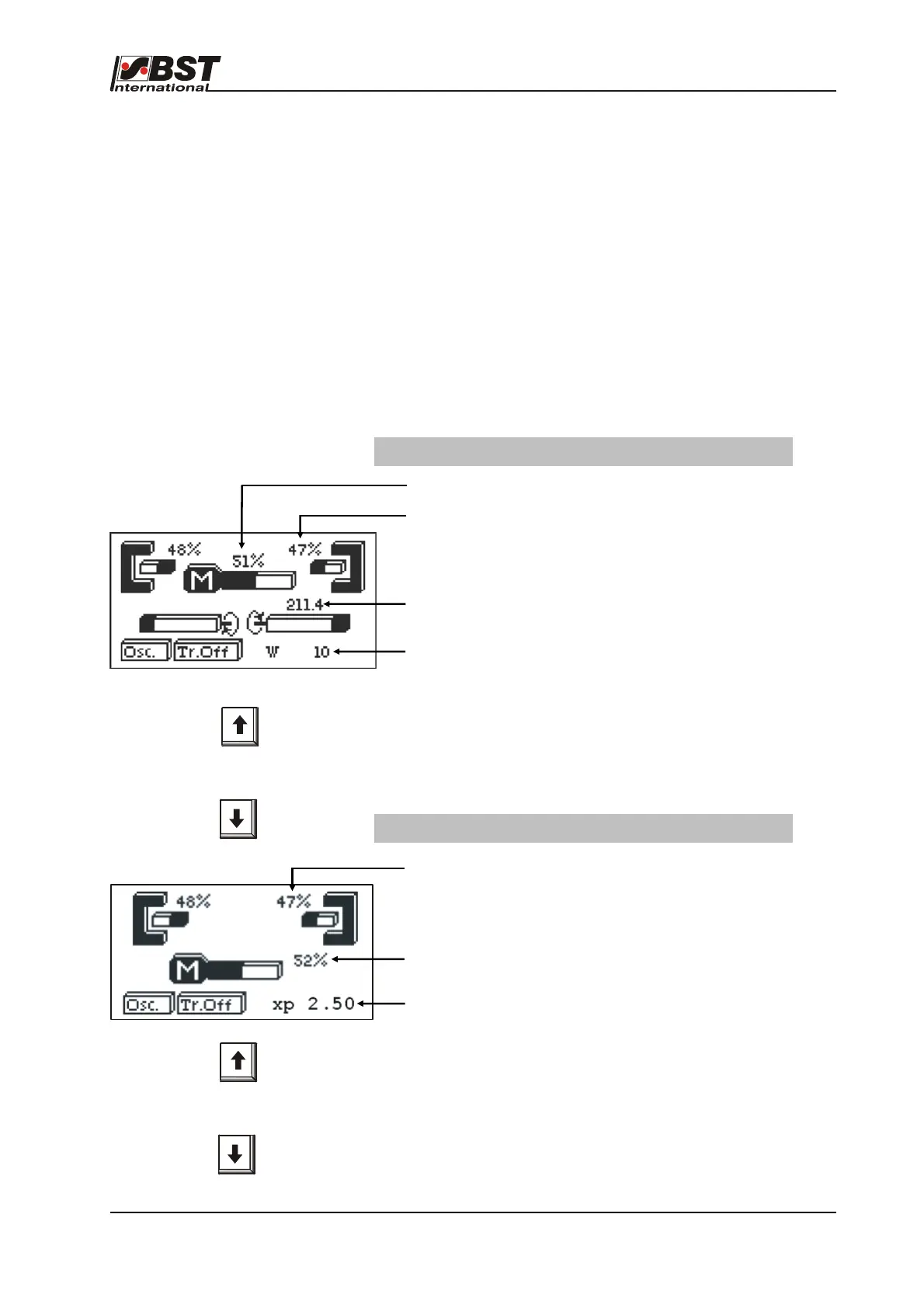
Screen without a sensor positioning device (FVG)
Switching between
operating displays
Display with sensor adjustment unit connected
Relative actuator position related to limit positions
Display of relative sensor scanning area coverage
Distance from sensor to external sensor positioning device
reference limit switch in mm
Controller setpoint (W) or controller gain (XP)
If you press the "SETUP“ key you will change between both
displays (W or XP).
The value displayed can be adapted in the "AUTO" operating mode
using the horizontal arrow keys.
Display of relative sensor scanning area coverage
Relative actuator position related to limit positions
Controller setpoint (W) or controller gain (XP)
If you press the "SETUP“ key you will change between both
displays (W or XP).
The value displayed can be adapted in the "AUTO" operating mode
using the horizontal arrow keys.
Switching between
operating displays