Commissioning example D 3
ekrPro Com
60
web guide controller EDV-No.: MD.191.01.05/1.6.x Appendix: D2
with analog sensors Date: 23.11.2007 Page: 4/4
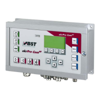
5. Check sensors connected and readjust it if necessary.
Check to ensure that the percentage display value increases the
more the sensor is covered. If not, check whether inverting is set.
After this, the Master setup for this sensor has to be carried out.
Press the F1 („auto“) button. Then cover up the sensor measuring
window completely and then hold it free. Press key F2 ("auto OK“)
to confirm.
6. Repeat the setting for Sensor 2.
If Sensor 3 is connected, no
master set up should be carried out.
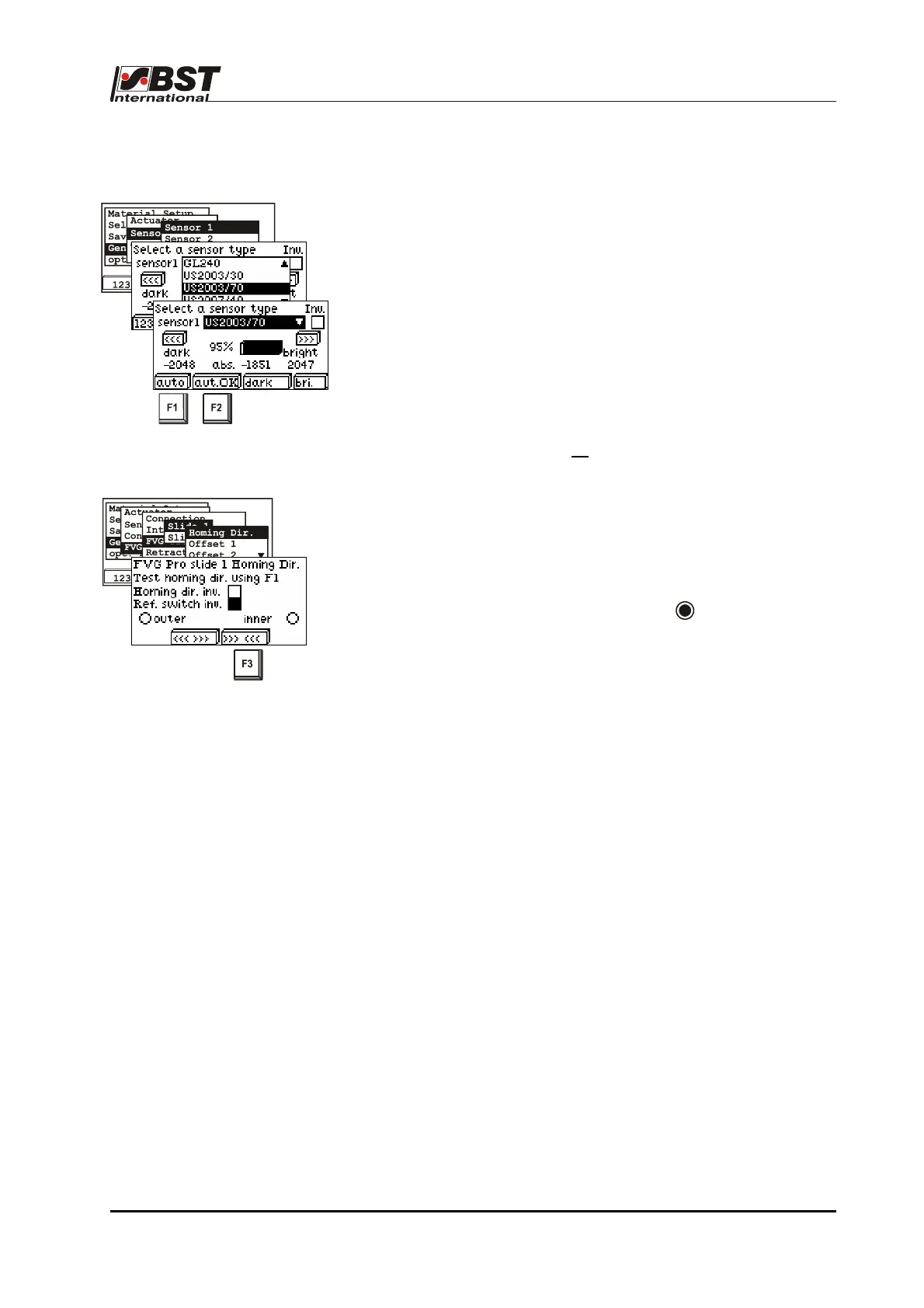
7. Check the FVG stepper motor and limit switch.
Check the FVG stepper motor rotation direction settings. Confirm
this position by pressing the F3 key. The checkbox “Homing dir.
inv.” must be activated if the traversing directions are reversed.
Now cover the external limit switch with a metal object (e.g. a coin).
The "outer“ radio button must be active ( ). If, instead of this, the
inner limit switch is shown as „active“, the checkbox "Ref. Switch
inv.“ must be activated.
Recheck both limit switches for safety reasons.
8. The settings carried out above for "Slide 1“ should now be
repeated for "Slide 2“.
9. Now, the FVGPro 2/MK has been made completely ready for
operation.
Once the basic settings have been made for the FVGPro 2/MK, you
can now carry out additional functionalities such as material width
measurement, pre-positioning etc.
These settings are described in the chapter entitled "Initial startup“,
Point B 3.7.5.5 "FVG – Sensor positioning device".