Apr. 2007
2
-31
DSC48
417W241A
417W240A
(1) Fan belt
(2) Hour meter unit
(3) Oil fi lter cartridge
(4) Filter support
(5) Alternator
(6) Oil gauge
(7) Exhaust manifold
(8) Oil switch
(9) Starter
B. DISASSEMBLY AND ASSEMBLY
► ENGINE BODY
Drain the oil and the water before disassembling the en-
gine body.
Exhaust manifold, starter, alternator, oil fi lter cartridge
1. Remove the muffl er and exhaust manifold (7).
2. Remove the starter (9) and oil switch (8).
3. Pull out the oil gauge (6).
4. Remove the alternator (5) and belt (1).
5. Remove the hour meter unit (2).
6. Loosen the oil fi lter cartridge (3) with a fi lter wrench and
remove it. Remove the fi lter support (4).
<When reassembling>
• Apply a liquid gasket to the thread of the oil switch.
• Apply a liquid gasket to both sides of the hour meter
unit gasket.
• Apply oil to the O-ring and tighten the oil fi lter cartridge
with a fi lter wrench.
• Adjust the fan belt tension.
3.3.2 EXTERNAL COMPONENTS
A. CHECKING AND ADJUSTING
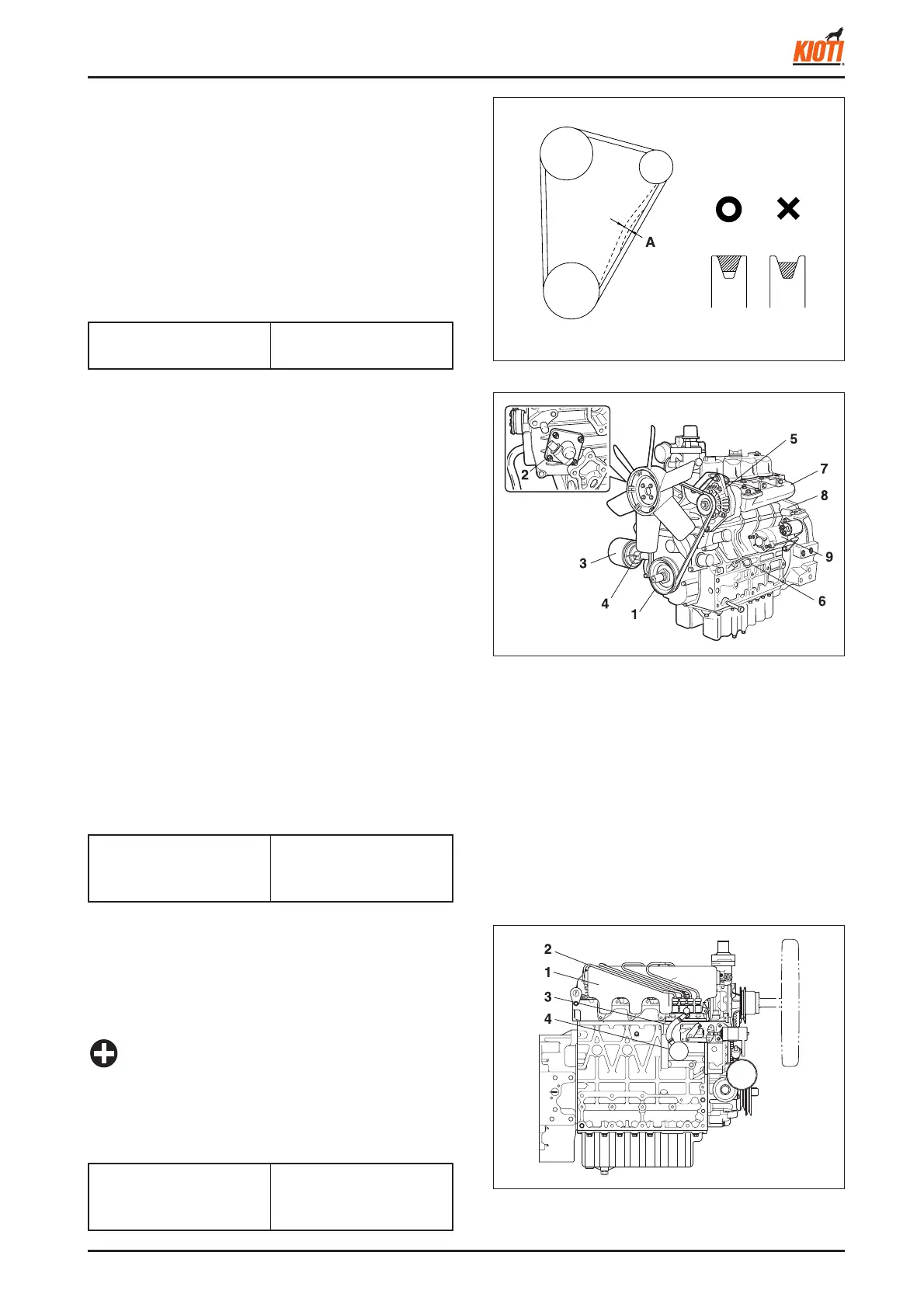
► FAN BELT
1. Measure the defl ection by depressing the belt halfway
between the fan drive pulley and alternator pulley at 10
kgf of force.
2. If the defl ection is not between the factory specifi cations,
loosen the bolts and nuts and move the alternator to adjust.
3. If the belt is damaged or worn, replace it.
(see fi gure)
Fan belt defl ection (A)
7 ~ 9 mm
0.276 ~ 0.354 in.
Oil switch tightening torque
14.7 ~ 19.6 Nm
1.5 ~ 2.0 kgf-m
10.8 ~ 14.5 lb-ft
417W242A
(1) Intake manifold
(2) Injection pipe
(3) Fuel pipe
(4) Fuel pump
► INTAKE MANIFOLD AND FUEL PIPE
1. Disconnect the fuel pipe (3).
2. Loosen the injection pipe fi tting with two spanners and
remove the injection pipe (2).
3. Remove the intake manifold (1) and fuel pump (4).
• Tighten or loosen the injection pipe fittings with two
wrenches held by one hand.
• Cap the nozzle hole to prevent entrance of foreign
materials.
IMPORTANT
Tightening torque
24.5 ~ 34.3 Nm
2.5 ~ 3.5 kgf-m
18.1 ~ 25.3 lb-ft