Apr. 2007
7
-27
DSC48
2
5.2. LIFTING AND LOWERING THE REAPING UNIT
A. LIFTING
1. When the lever is pushed to the lifting direction (rear-
ward), the lever and its lever point move around from
the pivot.
2. As the A section of the lever point pin moves, the reap-
ing unit height control lever switch moves to the left and
the switch for lifting comes on.
3. The reaping unit lifting relay in the threshing controller
is turned ON and supplies electric current to the reap-
ing unit lifting solenoid of the control solenoid valve.
4. The direction control solenoid valve is switched to the
reaping unit lifting position to raise up the reaping unit.
417W729A
B. LOWERING
1. When the lever is pushed to the lowering direction
(forward), the reaping unit height control lever switch
moves to the right and the switch for lowering comes
on.
2. The reaping unit lowering relay in the threshing con-
troller is turned ON and supplies electric current to the
reaping unit lowering solenoid of the control solenoid
valve to lower the reaping unit.
417W730A
(1) MICOM unit (2) Threshing controller
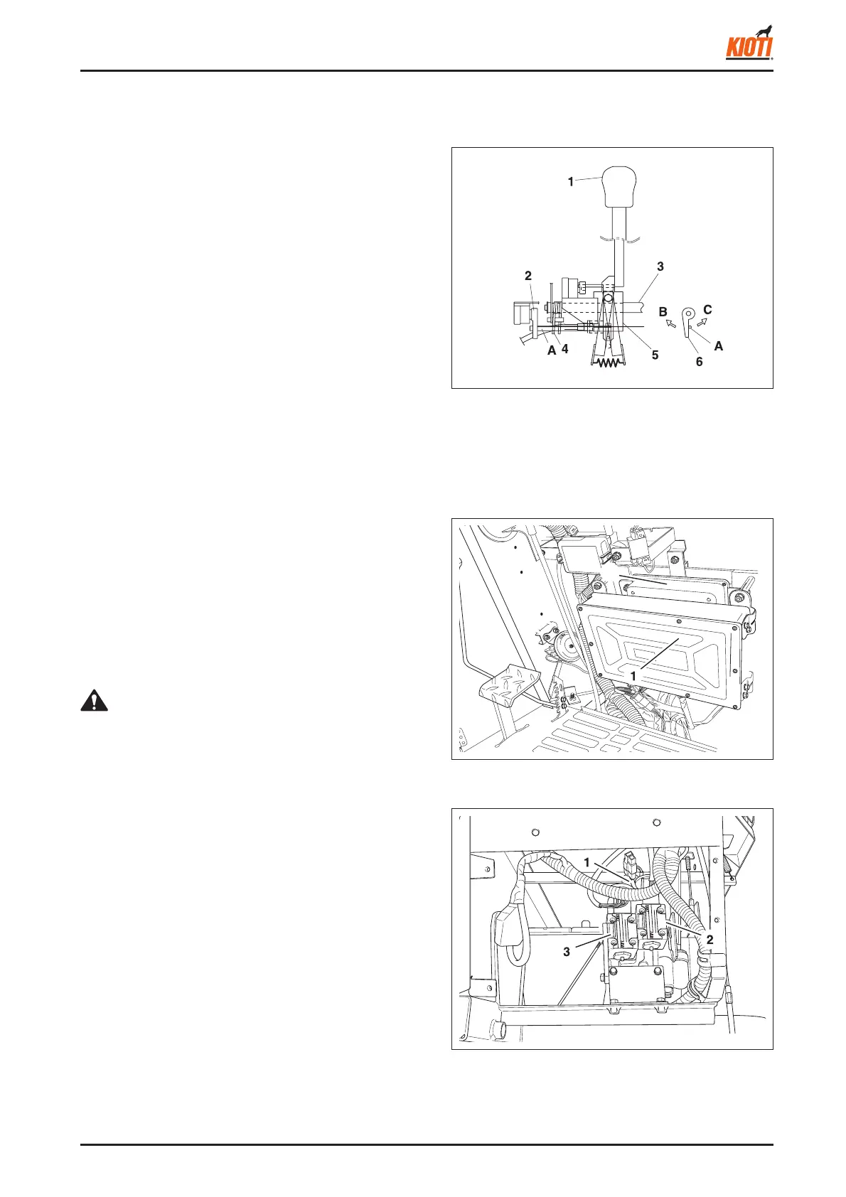
(1) Power steering lever
(2) Reaping unit height
control lever switch
(3) Pivot
(4) Return spring
(5) Lever point
(6) Reaping unit height
control lever switch
(B) Lowering
(C) Lifting
(1) Reaping unit lowering solenoid
(2) Steering control solenoid valve
(3) Reaping unit lifting solenoid valve
• The valve is solely controlled by electricity. Therefore,
when the ignition switch is in the "OFF" position, the
reaping unit cannot be lowered with the lever.
CAUTION
417W731A