Apr. 2007
6
-3
DSC48
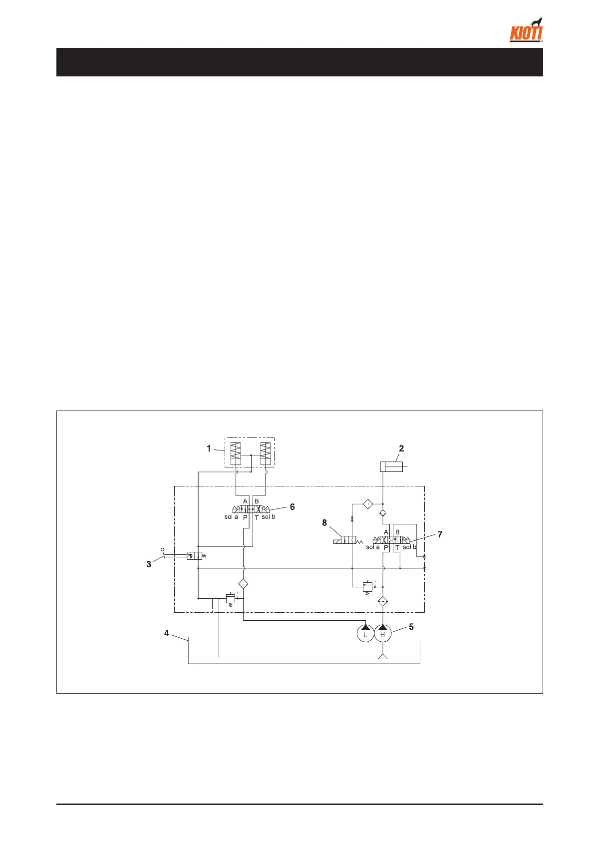
1.1 OVERVIEW
The hydraulic system in the combine harvester has three
major functions as below:
1. Lifting and lowering the reaping unit
2. Engaging/disengaging the steering clutch and operat-
ing the hydraulic brake
3. HST (Hydrostatic transmission)
The diagram shows the entire hydraulic system circuit,
except the HST.
Two hydraulic cylinders are assigned for the steering
clutch's engagement or disengagement and the hydraulic
brake, while another hydraulic cylinder is assigned for the
reaping unit's lifting up operation.
Also, each valve applies electric current to its solenoid to
operate the spool and control oil fl ow to each hydraulic
cylinder.
1.1.3 CIRCUIT DIAGRAM FOR HYDRAULIC SYSTEM
417W601A
The valve unit is composed of the solenoid valve and hy-
draulic block DH as one unit. It also protects the hydraulic
system by controlling the max. pressure in the system
with the low pressure relief valve (72~78 kgf/cm
2
) and
high pressure relief valve (149~161 kgf/cm
2
).
1.1.1 DIRECTION CONTROL SOLENOID
VALVE
The lifting and lowering operations of the reaping unit in-
volves one hydraulic pump. These operations have prior-
ity over other operations.
1.1.2 VARIABLE RELIEF VALVE
The variable relief valve is operated by the power steering
lever.
It can control the steering clutch cylinder's piston move-
ment by adjusting the pressure of the oil returning to the
oil tank from the steering clutch cylinders.
1. HYDRAULIC SYSTEM
(1) Steering clutch cylinders
(2) Reaping unit cylinder
(3) Steering lever
(4) Oil tank
(5) Gear pump
(6) Direction control solenoid valve
(7) Reaping unit lifting solenoid valve
(8) Reaping unit lowering solenoid valve