Apr. 2007
4
-35
DSC48
1
8
7
6
4
5
5
8
6
1
4
72
3
2
3
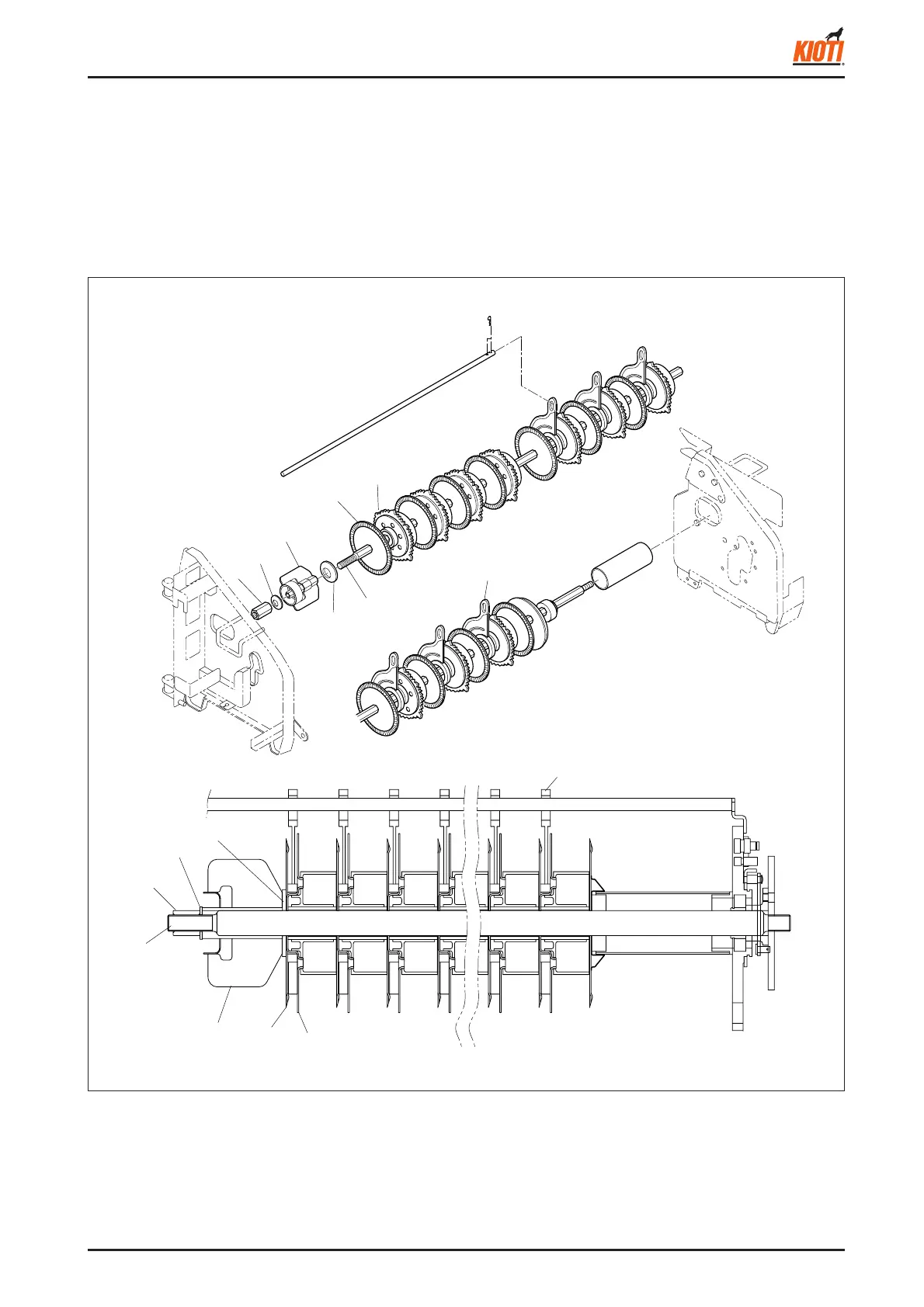
2.3.4 BASE DISC
1. Set a spanner (26 mm) to the hex. shaft of the dis-
charge wing 1 (7) and turn the hex. nut (RH, 1) to re-
move it.
2. Remove the spring washer 16 (6) from the discharge
wing 1.
417W487A
(5) Scraper (7) Discharge wing 1
(6) Spring washer 16 (8) Support washer 3
(1) Hex. nut (RH) (3) Feed loader 160
(2) Base disc 160 (4) Base shaft
<When assembling>
• Install the scraper guide to the 5th position seen from
the grain side (RH).
• The protrusion on the spring washer 16 should face
the right side of the hex. nut.
• Make sure to install the discs in the correct direction.
(Refer to the diagram below)