Apr. 2007
7
-33
DSC48
7.1 CHECKING EACH PART
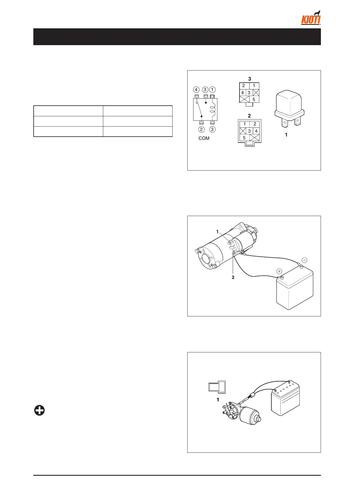
7.1.1 CHECKING AUTOMATIC ENGINE
STOP RELAY
1. Disconnect the connector and measure the resistance
at the relay side.
If the above values read, the relay is normal.
• If the relay is normal, check the connector and wiring.
417W734A
(1) Relay
(2) Relay side
(3) Wiring side
7.1.2 CHECKING STARTER
1. Connect the positive terminal to the starter B terminal.
2. Connect the negative terminal to the starter body.
3. Connect the B and S terminals with a screwdriver or
equivalent.
4. If the pinion driver gear is popped out, the starter is nor-
mal.
• If the starter is normal, check the wiring.
417W735A
(1) S terminal
(2) B terminal
7.1.3 CHECKING FEEDING DEPTH
CONTROL MOTOR
• Check whether the motor operates by connecting the
terminals to the battery. If the motor operates, it is nor-
mal.
• Do not connect several motors simultaneously.
417W736A
(1) Motor side
• If the motor is normal, check the connector and wiring.
• There is continuity between terminals.
IMPORTANT
2
1
7. ELECTRICAL SYSTEM
Between 5 and 1 Approx. 60
Ω
Between 2 and 4 Continuity
Between 2 and 3 Approx. 260
Ω