2
-32
Apr. 2007
DSC48
417W243A
3.3.3 ENGINE BODY
A. CHECKING AND ADJUSTING
► COMPRESSION PRESSURE
1. Run the engine until warmed up.
2. Stop the engine and remove the air cleaner, muffler
and nozzle holders.
3. Install the adapter to the nozzle holder and secure the
compression tester.
4. Pull the stop lever to cut the fuel and run the engine
with the starter at 250 ~ 270 rpm for 5 ~ 10 seconds.
5. Measure the maximum pressure for several times dur-
ing the engine's rotating.
6. If the measured pressure is not within the allowable limit,
apply a small amount of oil to the cylinder wall through
the nozzle holder hole and check the pressure again.
7. If the pressure rises after oil is applied, check the cylin-
der wall and piston ring.
8. If the pressure is still low, check the top clearance,
valve clearance and cylinder head.
• Check the compression pressure with the specified
valve clearance for proper air in taking.
CAUTION
Compression
pressure
Factory spec. 33 ~ 38 kgf/cm
2
Allowable limit 26 kgf/cm
2
Difference be-
tween cylinders
Allowable limit Within 10 %
417W245A
417W244A
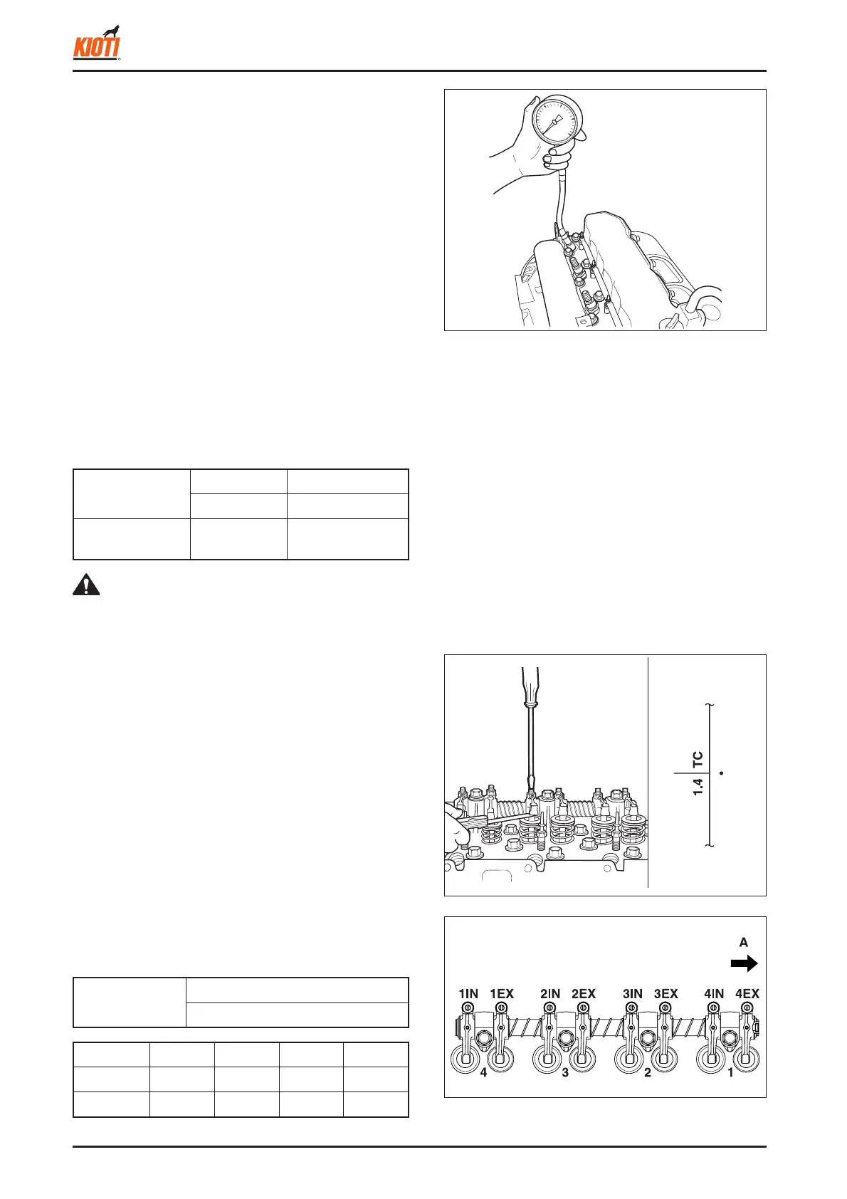
► VALVE CLEARANCE
1. Remove the cylinder head cover, timing cover of the
fl ywheel housing, and all of the glow plugs.
2. Turn the fl ywheel to align the 1 TC or 1.4 TC mark with
the timing mark on the engine installation plate so that
the No. 1 piston is at the top dead center during com-
pression.
3. Measure the clearance of the valves marked with "
{
in
the table below with a feeler gauge.
4. If the clearance is not within the factory specifi cations,
turn the adjusting screw to adjust it.
5. Rotate the fl ywheel just one turn to position the No. 1
cylinder at the overlap stage.
6. Measure the clearance of the valves marked with "
z
"
in the table below with a feeler gauge.
7. If the clearance is not within the factory specifi cations,
adjust it.
(A) Gear case
Valve clearance
IN.: 0.25 mm 0.010 in.
EX.: 0.30 mm 0.012 in.
Cylinder No. 1 2 3 4
Valve IN. EX. IN. EX. IN. EX. IN. EX.
Inspection
{{{zz{zz