Apr. 2007
2
-33
DSC48
417W246A
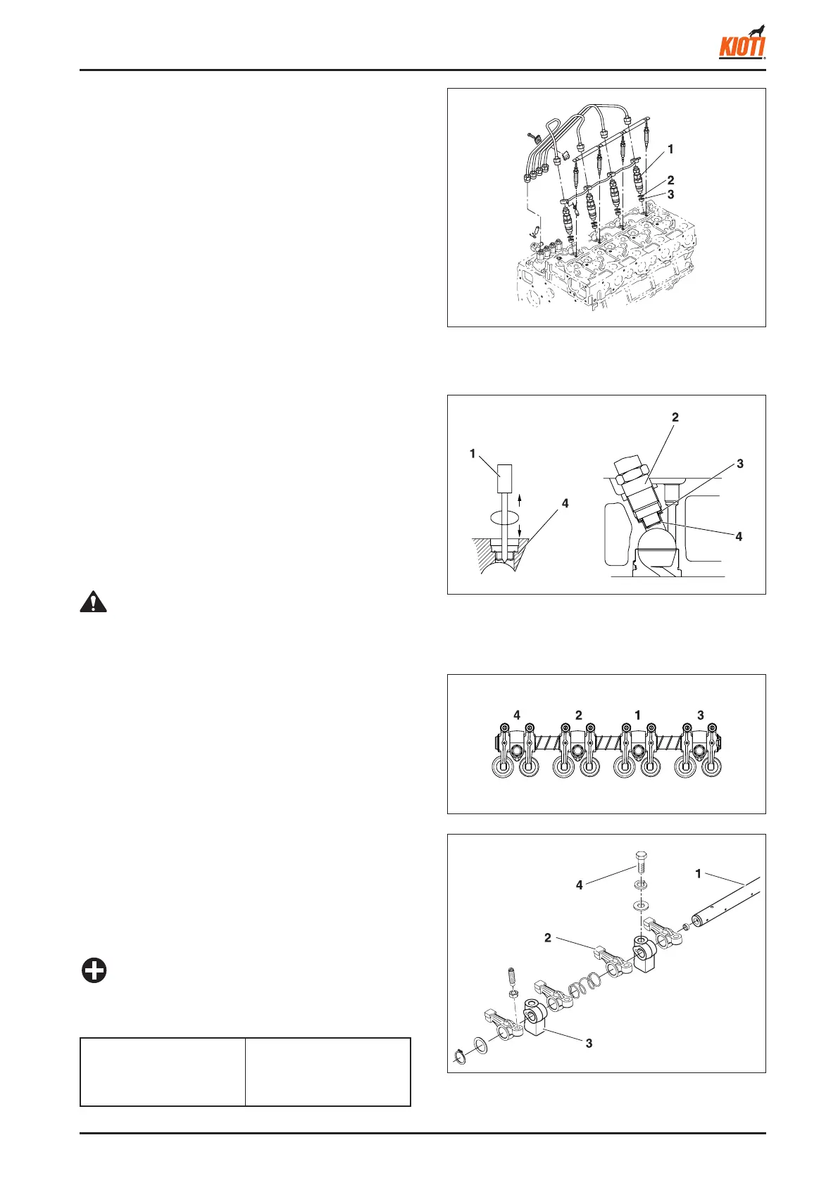
(1) Injection nozzle (3) Heat seal
(2) Gasket
3.3.4 DISASSEMBLY AND ASSEMBLY
A. CYLINDER HEAD AND VALVES
► CYLINDER HEAD COVER AND INJECTION NOZZLE
1. Remove the injection pipes and overfl ow pipe.
2. Remove the glow plugs.
3. Remove the injection nozzles and gaskets.
4. Remove the heat seals.
5. Remove the head cover.
<When reassembling>
• Check that the cylinder head cover gasket is not defec-
tive.
417W249A
417W248A
417W247A
(1) Screw driver (3) Nozzle gasket
(2) Injection nozzle (4) Heat seal
(1) Rocker arm shaft (3) Rocker arm bracket
(2) Rocker arm (4) Bolt
► HEAT SEAL REMOVAL PROCEDURE
1. Insert a Phillips screwdriver gently into the heat seal
hole.
2. Turn the screwdriver three or four times to the right and
left.
3. While turning the screwdriver, slowly pull the heat seal
and nozzle gasket.
If the heat seal drops, repeat the above procedure.
4. The heat seal and nozzle gasket should be replaced
when the nozzle is removed.
► ROCKER ARM ASSEMBLY
1. Loosen the bolts in the specified sequence shown in
the fi gure.
• To loosen: (4) to (1)
• To Tighten: (1) to (4)
2. Remove the rocker arm assembly and push rod.
<When reassembling>
• Place the push rod's end at the tappet's groove. Install
the rocker arm assembly.
• Tighten the blots step by step and in the specifi ed se-
quence to the specifi ed torque as shown in the fi gure.
• Adjust the valve clearance after assembling the rocker
arm assembly.
• When assembling the rocker arm assembly, locate the
groove of the rocker arm shaft on the stud bolt.
IMPORTANT
• Use a screw driver that its diameter is bigger than the
heat seal hole (approx.
φ
6 mm).
CAUTION
Tightening torque of
stud bolt
48.1 ~ 55.9 Nm
4.9 ~ 5.7 kgf-m
35.4 ~ 41.2 lb-ft