2
-8
Apr. 2007
DSC48
417W215A
417W214A
417W213A
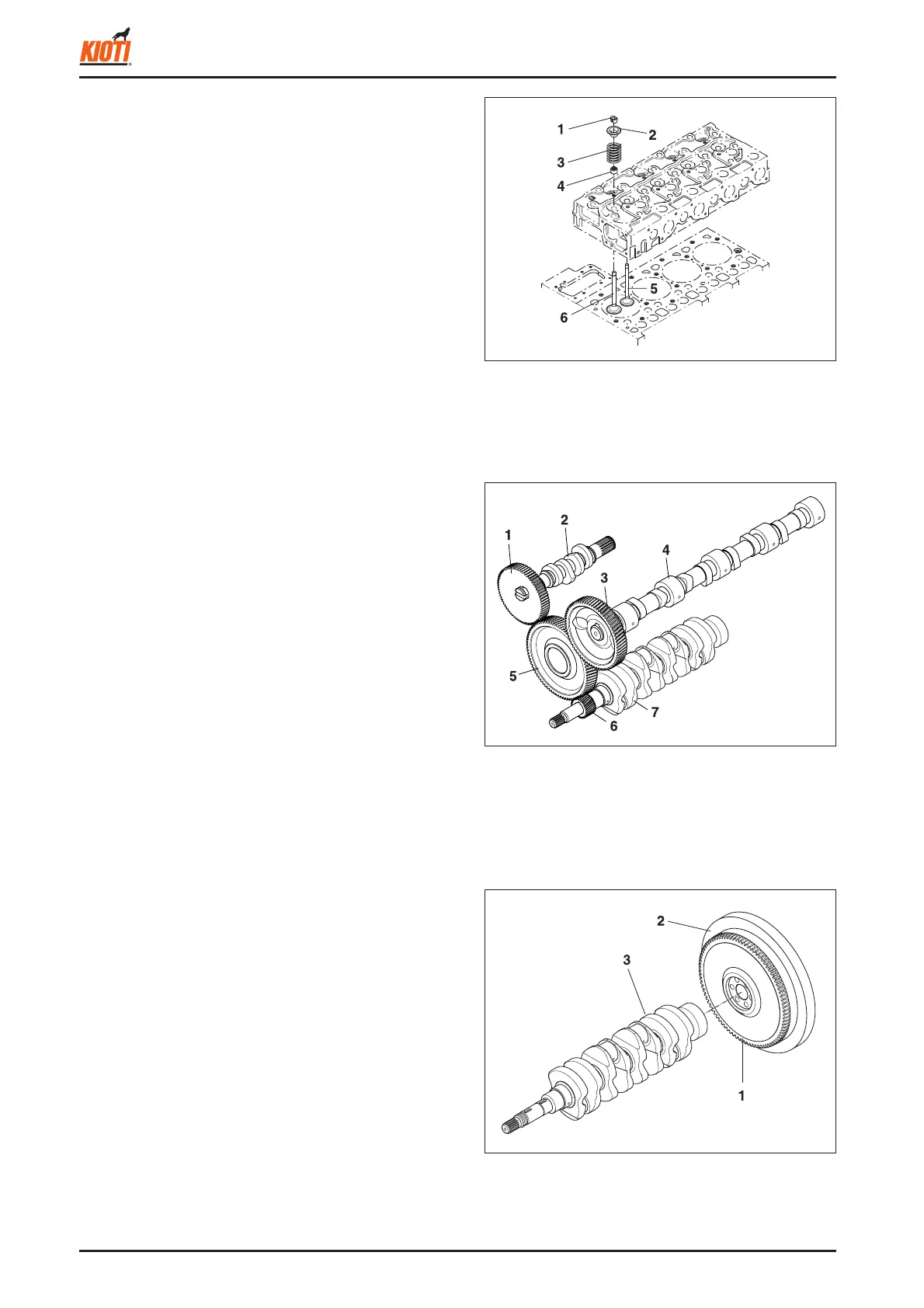
(1) Valve collet (4) Valve stem seal
(2) Valve spring retainer (5) Exhaust valve
(3) Valve spring (6) Intake valve
(1) Injection pump gear (5) Idle gear
(2) Fuel camshaft (6) Crankshaft gear
(3) Camshaft gear (7) Crankshaft
(4) Camshaft
(1) Ring gear
(2) Flywheel
(3) Crankshaft
2.1.11 FLYWHEEL
The fl ywheel is installed on the rear end of the crankshaft.
Its inertia keeps the engine turning at a constant speed.
while the crankshaft tends to speed up during the power
stroke and to slow down during the other strokes. The
fl ywheel has a ring gear (1), which meshes with the drive
pinion of the starter. The fl ywheel has marks "TC" and "FI"
on its outer rim. The mark TC shows the piston's top dead
center and the mark FI shows the fuel injection timing,
when they are aligned with the mark of the window on the
clutch housing.
Ú
Injection sequence
1
→
3
→
4
→
2
2.1.9 INTAKE AND EXHAUST VALVES
The valve and its guide of the intake are different from
those for the exhaust. Other parts, such as the spring (3),
spring retainers (2), valve spring collets (1), valve stem
seals (4) are the same for both the intake and the exhaust.
All contact or sliding surfaces are hardened to increase
wear resistance.
2.1.10 TIMING GEAR
The crankshaft gear drives the oil pump and rotates the
idle gear, fuel camshaft gear, and camshaft gear. The
timing for opening and closing the valves is extremely im-
portant to achieve effective air intake and suffi cient gas ex-
haust. The appropriate timing can be obtained by aligning
the marks on the crankshaft gear with the idle gear, the idle
gear with the camshaft gear, the idle gear with the injection
pump gear, when assembling.