Apr. 2007
7
-25
DSC48
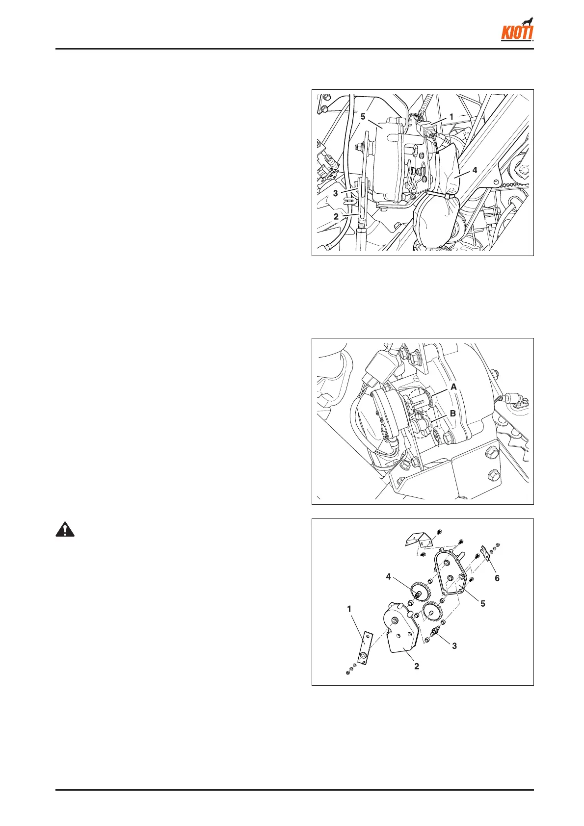
4.6.1 REMOVAL OF FEEDING DEPTH
CONTROL MOTOR
1. Disconnect the feeding depth control wiring (1).
2. Remove the pin (3) from the end of the feeding depth
control rod (2).
3. Remove the feeding depth control motor (4) and feed-
ing depth control rotation case (5) as a unit.
4.6 REMOVAL OF FEEDING DEPTH CONTROL MOTOR AND LIMIT SWITCH
417W724A
(1) Feeding depth con-
trol wiring
(2) Feeding depth con-
trol rod
(3) Pin
(4) Feeding depth con-
trol motor
(5) Feeding depth con-
trol rotation case
4.6.2 FEEDING DEPTH CONTROL
MOTOR AND LIMIT SWITCH
1. Unscrew two mounting bolts to remove the feeding
depth control motor and limit switch.
<When assembling>
• When installing the motor, engage the output shaft end
of the feeding depth control motor with the split section
of the feeding depth adjustment drive arm (A in fi gure).
Also, connect the protrusion on the limit switch (depth
stop switch) shaft to the protrusion on the feeding depth
control rotation shaft. The feeding depth control rotation
arm should be under the feeding depth control rotation
case.
417W725A
417W726A
(1) Feeding depth control rotation arm
(2) Feeding depth control rotation case 1
(3) Feeding depth control rotation shaft 1
(4) Feeding depth control rotation shaft 3
(5) Feeding depth control rotation case 2
(6) Feeding depth adjustment drive arm
• Cautions when removing feeding depth control rotation
case
When removing the feeding depth control rotation case,
put identifi cation marks on the rotation cases 1, 3 and
their arms so that the locational relation between the
feeding depth control rotation arm and feeding depth
adjustment drive arm can be easily identifi ed later.
CAUTION