Apr. 2007
6
-5
DSC48
A
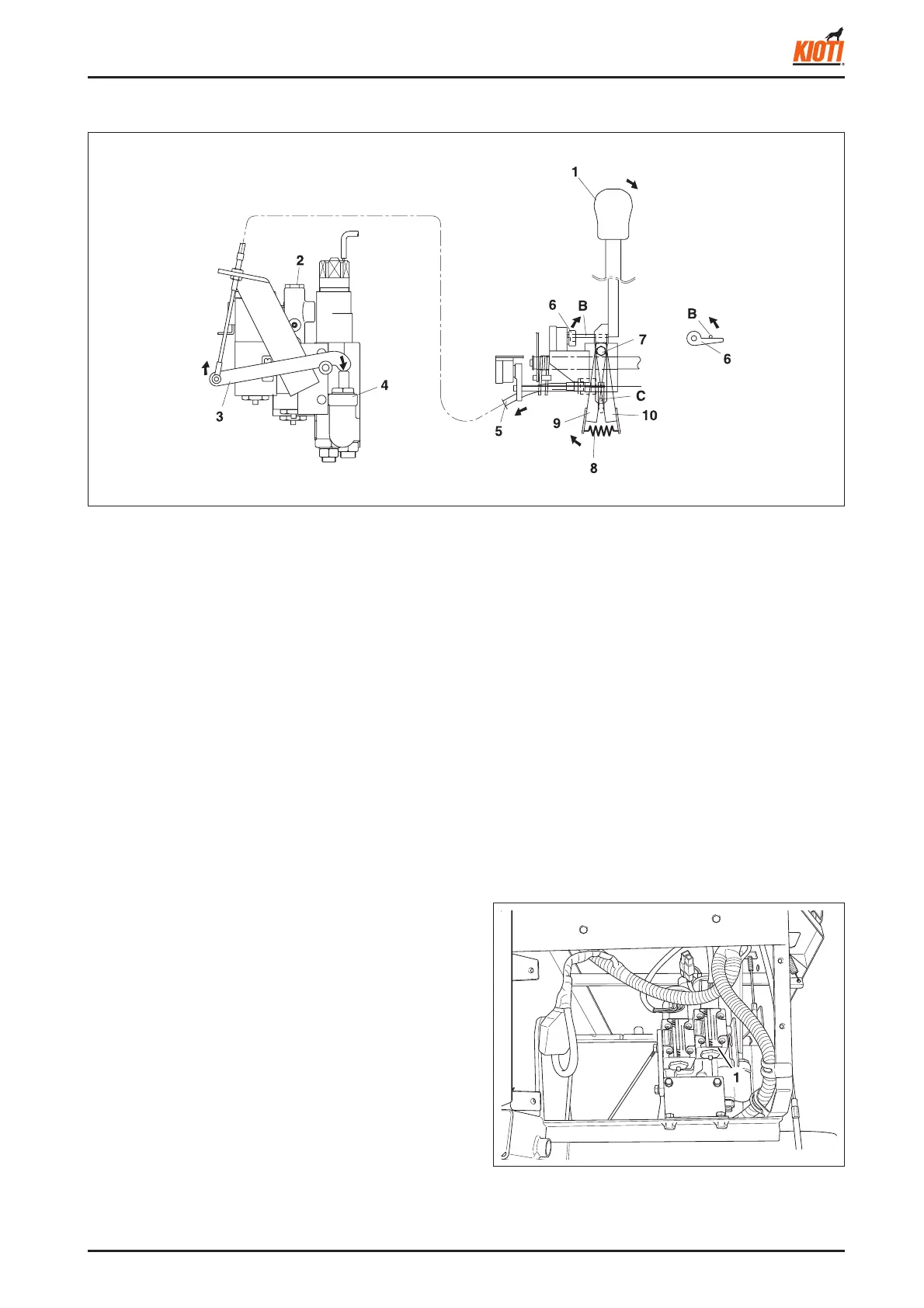
1.2.2 TURNING AND CORNERING
417W604A
(1) Power steering lever
(2) Valve unit
(3) Brake arm
(4) Variable relief valve
417W605A
(1) Steering control solenoid
B. LEFT TURN
The direction control lever switch moves to the right and
turns on the left turn switch. Then, electric current fl ows to
the left turn solenoid of the steering control solenoid. Also,
as the C section of the lever pin moves, the brake arm (RH)
is pressed to the right side, the inner power brake cable is
pulled, and the variable relief valve is pressed.
5. At the same time, the brake arm (LH) is pressed to
the left side and the outer power brake cable is pulled
as the C section of the lever pin moves. The inner
cable is fi xed to the brake arm (RH).
6. he brake arm of the valve unit is turned to the left
by the inner cable and pushes in the variable relief
valve. Therefore, the oil pressure in the right steering
clutch cylinder rises and powerfully pushes its piston.
7. After disconnecting the steering clutch, the piston ac-
tivates the brake. The more inclination the lever has,
the more the valve is pushed in to increase the braking
power.
A. RIGHT TURN
1. When the lever is pushed to the right, the lever moves
around from the point bolt.
2. As the B section of the lever point pin moves, the direc-
tion control lever switch moves to the left and turns on
the switch on the right.
3. The relay unit supplies electric current to the right turn
solenoid of the steering control solenoid valve.
4. The right steering clutch cylinder's piston cuts its
clutch's power.
(5) Power brake cable
(6) Direction control lever
switch
(7) Point bolt
(8) Brake return spring
(9) Brake arm (LH)
(10) Brake arm (RH)
(A) Right turn
(B) Lever point pin
(C) Lever pin