Apr. 2007
4
-27
DSC48
1
1
2
1
3
3
2.1.2 REMOVAL AND INSTALLATION
A. PRECEDING WORK BEFORE REMOVING
STRAW DISCHARGING CONVEYOR CASE
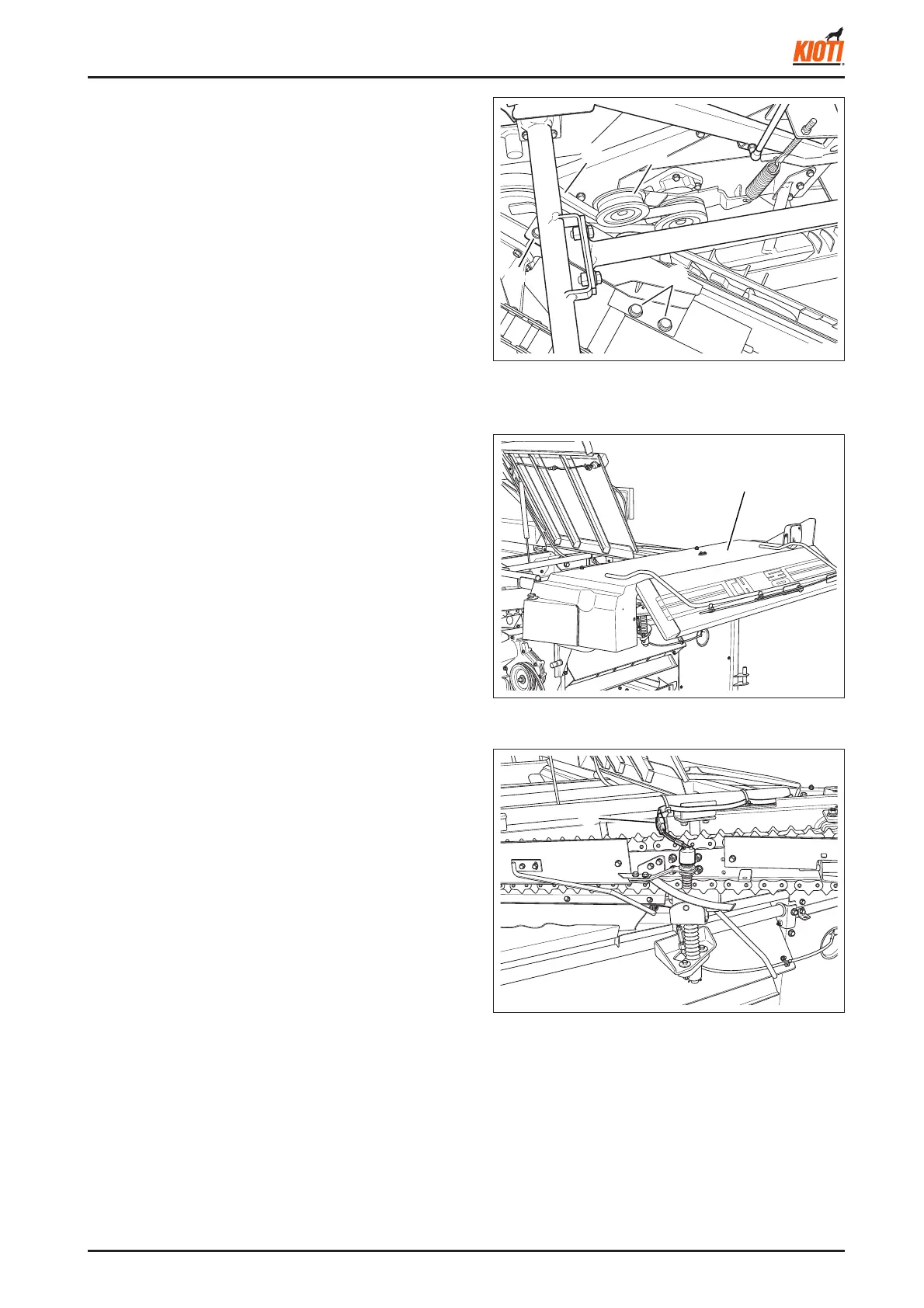
1. Remove the tension arm and pull out the belt.
2. Unscrew the bolt which puts the upper frame 2 and
bevel case together and two mounting bolts on the up-
per frame 2 and grain side conveyor case.
(1) Tension arm (3) Bolt
(2) Belt
417W464A
(1) Upper cover 1
417W465A
B. UPPER COVER 1
1. Open the cutter.
2. Disconnect the connector from the upper cover 1.
3. Remove the bolt on the upper cover 1 to remove the
cover.
C. CONVEYOR CASE ASSEMBLY
1. Remove the oil hose.
2. Disconnect the 2P connector (1) from the straw dis-
charging sensor.
3. Remove the conveyor case assembly by pulling it to
the rear side (cutter side).
417W463A
(1) Connector