Apr. 2007
6
-15
DSC48
1.7 REMOVAL AND INSTALLATION
1.7.1 REMOVAL OF VALVE UNIT
Power brake cable, clutch pedal rod, wiring, and hydraulic
hoses
1. Remove the step cover (FR).
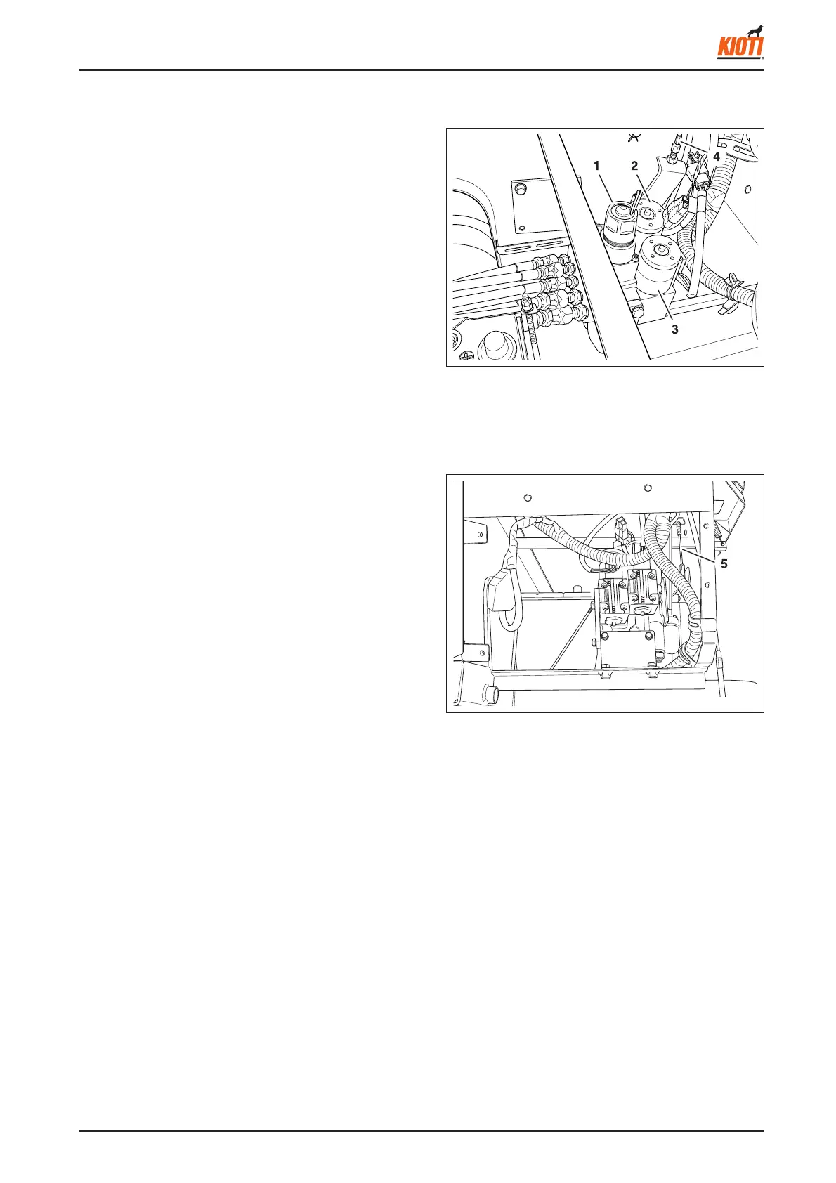
2. Disconnect the power brake cable (4).
3. Disconnect each solenoid valve's connector (3 EA).
4. Disconnect fi ve hydraulic hoses from the valve unit. (It
is recommended to mark on the hoses to connect them
to the correct locations later.)
417W618A
(1) Reaping unit lowering solenoid valve
(2) Steering control solenoid valve
(3) Reaping unit lifting solenoid valve
(4) Power brake cable
<When assembling>
• Engage the connectors to the connectors with the same
colored tapes.
[Cellophane tape color of connectors]
Steering control solenoid valve (2): (No tape)
Reaping unit lifting solenoid valve (3): Red
• Engage the connector of the low speed side (rear) of
the reaping unit lowering solenoid valve (1) to the main
wiring connector.
A. REAPING UNIT LOWERING SOLENOID VALVE
• Tie the wirings of the direction control solenoid valve,
reaping unit lifting solenoid valve, and the brake switch
with the cord band.
• Adjust the power brake cable (4) after installation.
(see page 5-13)
• Make sure to connect the hoses to the correct location
referring to the fi gure on the right.
(5) Power brake cable