Apr. 2007
4
-13
DSC48
1
2
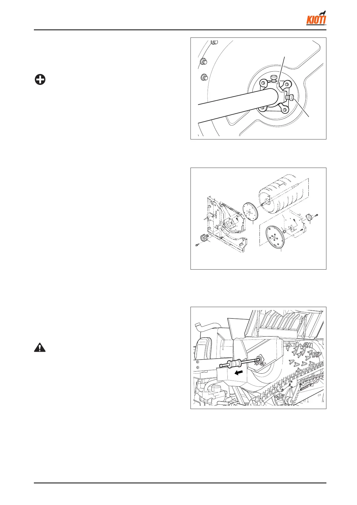
9. Open two disc type covers which are close to the cir-
cumference joint of the threshing cylinder. Unscrew
one mounting bolt on the threshing cylinder boss 1
(front) and two mounting bolts on the threshing cylin-
der boss 2 (rear).
(1) Threshing cylinder boss 2
(2) Mounting bolt
<When assembling>
• The clearance between the threshing cylinder and side
plate should be approx. 15 mm. The side plate should
not contact with the straw chopper blade.
• Apply LOCTITE to the mounting bolt.
IMPORTANT
417W422A
3
4
1
2
5
<When assembling>
• Apply grease in the threshing cylinder boss. Align the
key of the shaft to the key groove and tap on the shaft
to insert it.
• When installing the threshing cylinder shaft, tighten the
nut on the shaft to be aligned with the shaft and tap the
shaft with a urethane hammer to insert it.
• After installation, rotate the threshing cylinder several
times and check whether or not the threshing cylinder
stops at the same position after each rotation (Weight
balance check).
• When removing the shaft, make sure that its key does
not get caught.
CAUTION
417W423A
(1) Bearing holder (front) (4) Anti-drop plate 1 (front)
(2) Bearing holder (rear) (5) Anti-drop plate 2 (rear)
(3) Spacer
10. Unscrew the bolt on the bearing holder 2 (rear) and
remove the holder. Do not loosen the adjusting bolt.
When removing the bearing holder 2 (rear), remove
the spacer with it.
11. Unscrew the bolt on the bearing holder 1 (front).
12. Unscrew seven mounting bolts (arrow) on the front
anti-drop plate 1 and fi ve mounting bolts on the rear
anti-drop plate 2.
417W425A
13. Remove the threshing cylinder shaft by tapping it to
the front side. Insert a long pole (1 m) into the hole on
the rear side and tap it to remove the shaft. The shaft
can be easily pulled out comes out with a special
puller.