Apr. 2007
4
-17
DSC48
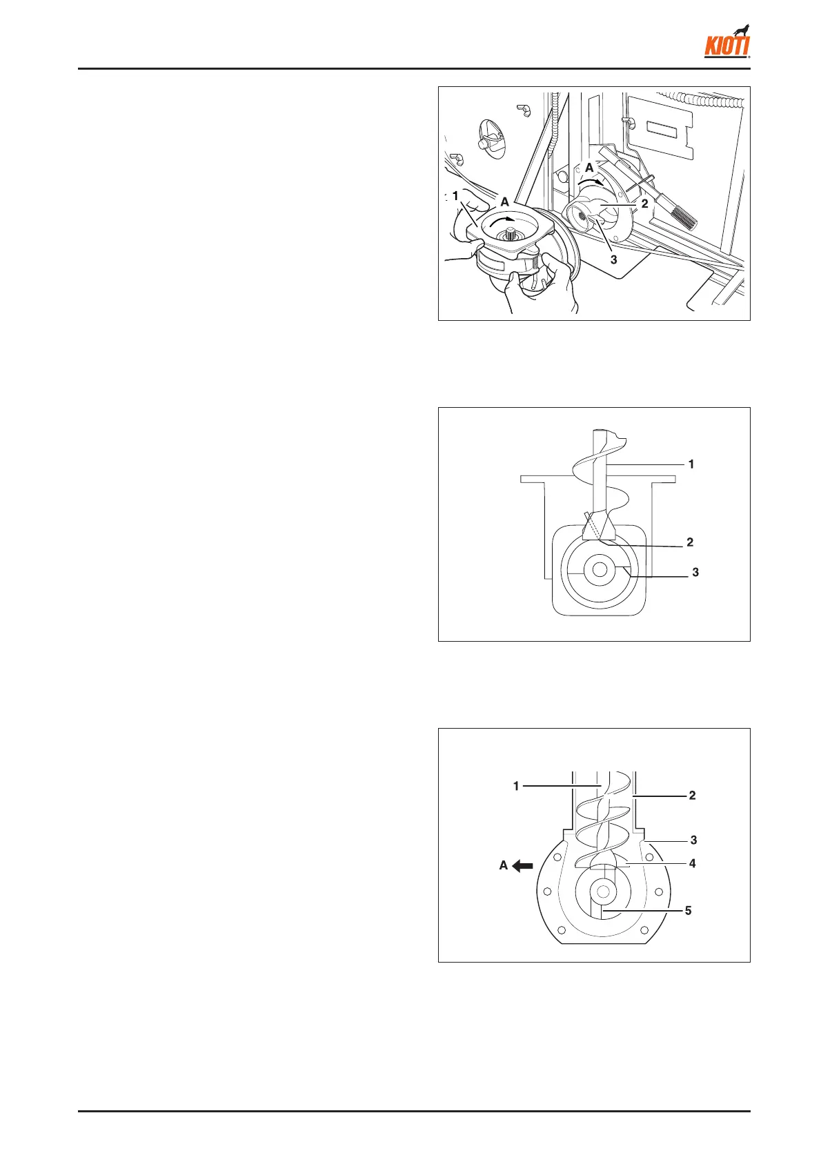
5. Remove the No. 1 bevel case.
6. Remove the No. 1 auger.
(1) No. 1 bevel case (A) Rotating direction
(2) No. 1 screw
(3) No. 1 blade edge
<When assembling>
1. Secure the edge of the No. 1 auger blade end to be
perpendicular to the combine harvester front-rear direc-
tion.
417W433A
(1) No. 1 blade shaft
(2) No. 1 auger blade end
(3) Horizontal auger top end
417W434A
(1) Horizontal auger shaft
(2) Horizontal auger case
(3) No. 1 bevel case
(4) Horizontal auger top end
(5) No. 1 auger blade top end
(A) Combine harvester's front or rear end
417W432A
2. Secure the horizontal auger blade end to be parallel
with the combine harvester's front-rear direction.
3. When installing, turn the horizontal auger to check any
possible interference.