Apr. 2007
2
-15
DSC48
417W229A
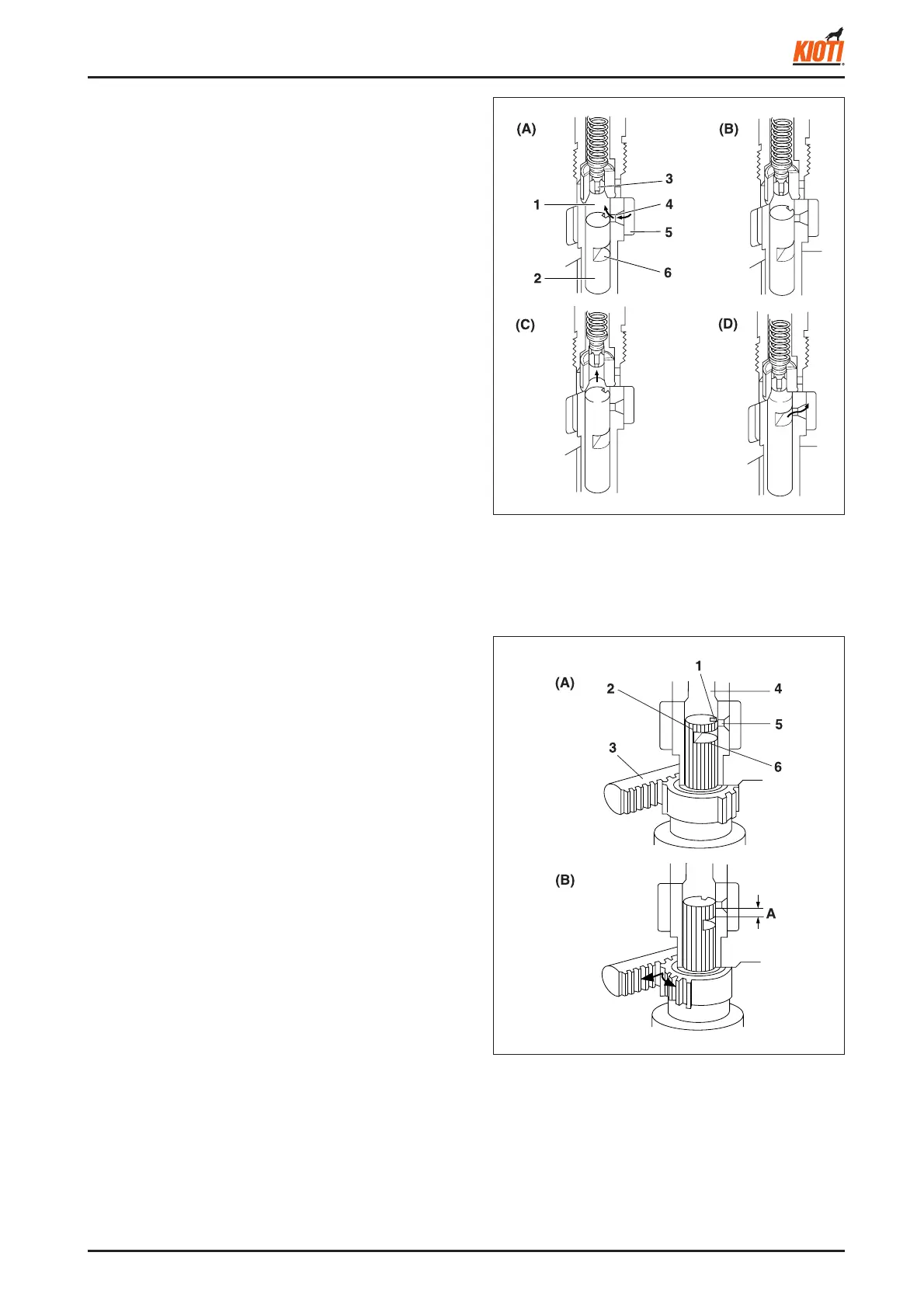
(1) Delivery chamber (4) Feed hole
(2) Plunger (5) Fuel chamber
(3) Relief plunger (6) Control groove
B. OPERATION OF PUMP ELEMENT
(A) Before fuel compression
As the tappet lowers, the plunger (2) lowers and the fuel is
drawn into the delivery chamber (1) through the feed hole (4)
from the fuel chamber (5).
(B) Beginning of fuel compression
When the plunger is pushed up by the cam and the head
of the plunger closes the feed hole (4), the pressure in the
delivery chamber rises to push the relief plunger (3).
(C) Fuel compression
While the plunger is rising, the fuel injection continues.
(D) End of fuel compression
When the plunger rises further and the control groove (6)
meets the feed hole, the fuel returns to the fuel chamber
from the delivery chamber through the control groove and
feed hole.
417W230A
(1) Slot (4) Delivery chamber
(2) Plunger (5) Feed hole
(3) Control rack (6) Control groove
C. AMOUNT OF FUEL DELIVERED
(A) No fuel delivery
At the engine stop position of the control rack (3), the
lengthwise slot (1) on the plunger (2) aligns with the feed
hole (5). The delivery chamber (4) is led to the feed hole
during the entire stroke of the plunger. The pressure in the
delivery chamber does not build up and no fuel is forced to
the injection nozzle.
(B) Fuel delivery
The plunger is rotated by the control rack and the feed hole
is not aligned with the lengthwise slot. When the plunger
is pushed up, the feed hole is closed by the plunger. The
pressure in the delivery chamber builds up and forces
the fuel to the injection nozzle until the control groove (6)
meets the feed hole. The amount of the fuel to be forced
into the nozzle corresponds to the distance A.