Working with These Operating Instructions Chapter 1 - Introduction
Apollo Operator’s Manual 3
Part Number: 90 38 237, 6th edition
Working with These Operating
Instructions
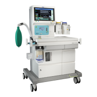
Figure 1. Example of a Body Page
Header Line
The header line on each page contains the title of the
chapter and the title of the subsection that begins on
that page. This helps you find your way quickly from
subject to subject.
Page Body
The page body in these Operating Instructions
combines text and illustrations. The information is
presented as sequential steps of action, giving the
user hands-on experience in learning how to use the
Apollo machine.
Left-Hand Column - the Text
The text in the left-hand column provides
explanations and step-by-step instructions on the
practical use of the machine.
Bullet points indicate separate actions. Numbers are
used both to refer to relevant details in the
illustrations and to specify the sequence of actions
where several actions are described.
Right-Hand Column - the Illustrations
The illustrations provide visual reference for the text
and for locating the various parts of the equipment.
Elements mentioned in the text are highlighted.
Renderings of screen displays guide the user and
provide a way to reconfirm actions performed.
Typing Conventions
User controls are designated as >Control Name<,
e.g.:
>PEEP<
Screen messages and screen options are printed in
bold, e.g.:
Default Alarm Limits
Overview Chapter 10 - Configuration
Apollo Operator’s Manual 149
Part Number: 90 38 237, 6th edition
Overview
The user can configure settings on the Apollo in
Standby mode as well as during operation. Standby
configuration allows the user to save a complete set
of defaults that are invoked automatically when the
machine is switched on (see “Configuring the Default
Settings in Standby” below). The configuration
settings that can be made during operation are more
limited and are valid only until the machine is
switched off (see “Configuration During Operation”
on page 162).
Configuring the Default Settings in
Standby
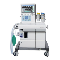
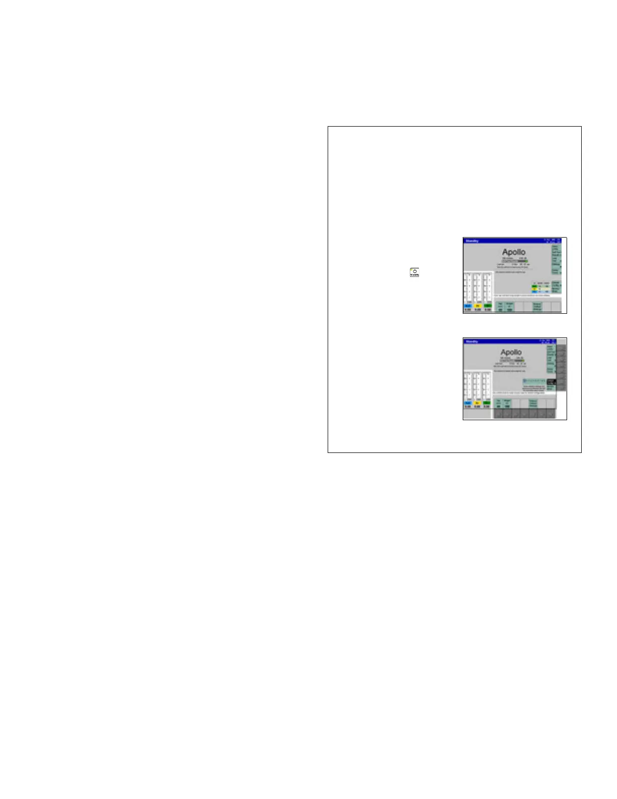
Figure 111. Location of Standby Config KeyThe default settings are a set of saved ventilation,
gas monitoring, and alarm settings that are valid
whenever the machine is switched on and are
activated via the soft key >Restore Default
Settings< in the Standby screen.
To configure the default settings:
1. Press the standby key > <, and press the
confirm knob.
2. Press the >Default Config< soft key (1 in Figure
111).
The user is prompted to enter a password in
order to prevent unauthorized changes to basic
functions (see Figure 112). The 4-digit password
is assigned at the factory. If desired, the
password can be changed or the password
function can be disabled altogether by
DrägerService.
Figure 112. Password Screen3. Turn the confirm knob to select the first digit of
the password, and press the knob to confirm.
Continue entering the remaining password digits
in the same manner. The password is
represented as a line of asterisks (****) below the
numbers.
When the password is entered correctly, the first
configuration screen is displayed (Figure 113.).
The configured values are effective immediately.
1