System LED Indicators Chapter 3 - User Interface
Apollo Operator’s Manual 35
Part Number: 90 38 237, 6th edition
System LED Indicators
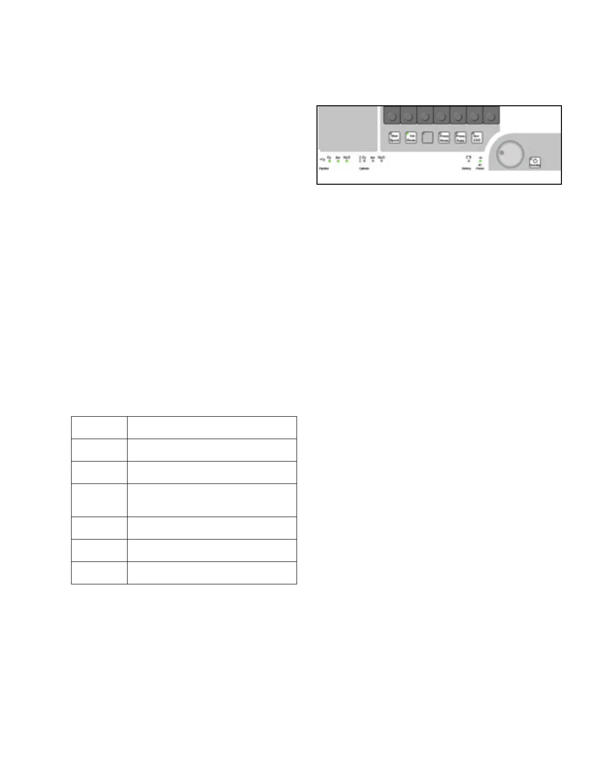
Figure 17. LED Indicators
A number of LED indicators are located at the bottom
of the front panel. They can light up green or red, or
can remain extinguished, to indicate gas supply and
machine power status.
The pipeline supply LEDs (1 in Figure 17 ) can be
either green, which indicates pipeline is connected
and pressure is adequate, or off (extinguished). If the
pipeline pressure transducer is inoperable, the
corresponding LED will flash green.
If the backup gas cylinder is connected and pressure
is adequate, the corresponing LED (2 in Figure 17)
will be green. If the backup gas cylinder is
connected, but the pressure is inadequate and the
pipeline supply is not available, the LED will flash
red. If the backup cylinder is not connected, the LED
will be dark (extinguished).
The Battery and AC Power LEDs (3 in Figure 17)
have two states: green or off (extinguished). The
LED that is green indicates the active power source.
Screen Colors
Colors are used on the screen to indicate the status
of soft keys and to highlight operating sequences.
Ventilation Soft Keys
The ventilation soft keys appear green when
operable and turn yellow when selected. Once the
value is changed and confirmed, the soft key turns
back to green.
1
3
2
Color Meaning
Green active, can be operated
Yellow selected, ready to set/confirm
Black
leads to another menu or operating
function
Gray not yet active, presettings
Orange highlights current selection
Gray type not available for selection