Chapter 4 - System Setup Connecting the Gas Supply
44 Apollo Operator’s Manual
Part Number: 90 38 237, 6th edition
Connecting the Gas Supply
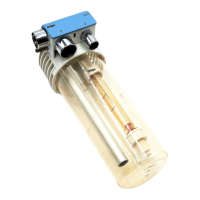
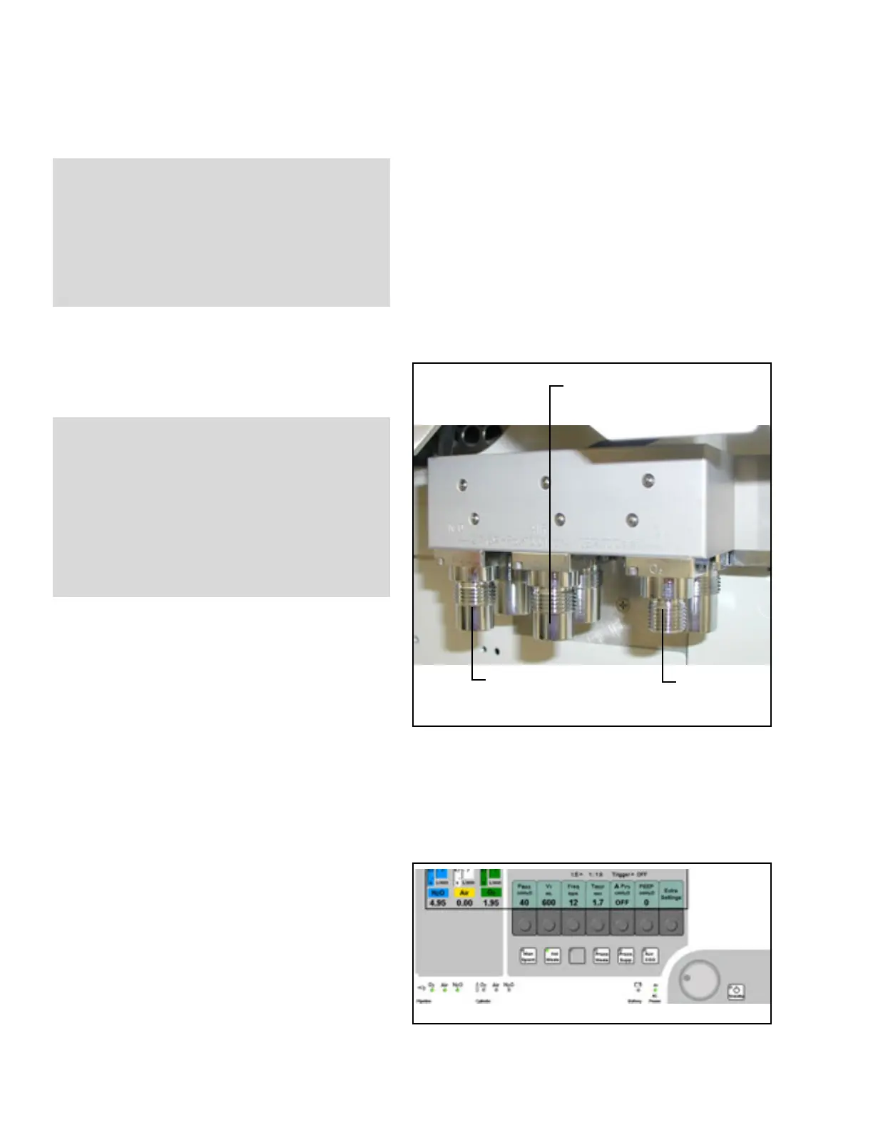
Figure 23. Pipeline ConnectionsConnecting Pipeline Supply of N
2
O, Air,
and O
2
1. Connect the gas fitting on each pipeline supply
hose to the corresponding fitting on the gas
supply block on the rear of the machine (see
Figure 23).
2. Connect the other end of each pipeline supply
hose to the appropriate functioning wall outlet.
3. Ensure that the pipeline pressures are between
50 and 55 psi (see “Operating Data” on page 210
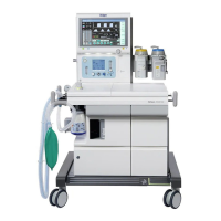
for ranges) by checking that the three pipeline
LEDs on the front machine panel (1 in Figure 24)
are illuminated green.
Figure 24. Location of Pipeline Pressure LEDsIf the pipeline pressure LEDs remain dark, it
means that the pressure is below 39 psi or that
the hoses are not connected properly.
WARNING !
Oil and grease may combine explosively with
oxygen or nitrous oxide. For this reason, oil and
grease must never come in contact with
pipelines, cylinders, cylinder valves, gauges,
fittings, etc., which conduct oxygen or nitrous
oxide within the machine.
N
2
O
Pipeline
Connection
O
2
Pipeline
Connection
Air
Pipeline
Connection
WARNING !
Carefully check hoses each time you connect a
machine to a wall outlet to ensure that both ends
of the hose are indexed for the same gas.
Pipeline delivery hoses used between wall
outlets and anesthesia machines have caused
accidents when, during assembly, an oxygen
fitting was placed on one end of the hose and a
nitrous oxide fitting on the other end.
1