Overview Chapter 3 - User Interface
Apollo Operator’s Manual 31
Part Number: 90 38 237, 6th edition
Overview
This chapter provides a description of the Apollo user
interface, which enables you to view and change
monitoring, ventilation, and status information using
keys and rotary knobs.
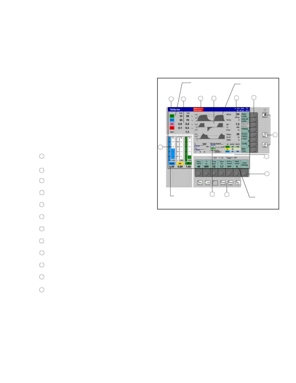
Figure 10. Standard Monitor Screen Layout
Main Screen Display
The screen display is organized into four functional
areas:
• gas measurement
• monitoring
• fresh gas delivery
• ventilation
Figure 10 illustrates the general functional areas and
identifies the following smaller screen elements:
User Controls
Changes to system settings and screen displays are
made using rotary knobs, “hard keys” (keys with
permanently defined functions), and “soft keys” (keys
with variable functions). All controls are described in
the following paragraphs.
Gas
Measurement
Monitoring
Delivery
1
2
3
4
5
7
Fresh Gas
8
10
12
11
6
Ventilation
Status field; displays information about the
current operating mode
Numeric field for gas and agent measurement
values
Alarm field; displays alarm messages
User-configurable graphics field for curves and
bar graphs
Numeric field for monitored parameter values
Monitoring/configuration soft keys
Standard function keys; for selecting monitoring
screens and silencing alarms
Prompt field; displays messages for the user
Ventilation parameter soft keys
Ventilation mode hard keys
User-configurable monitoring area
Fresh gas bar graphs (virtual flow tubes)
1
2
3
4
5
6
7
8
9
10
11
12